Dell PowerEdge 4300 Dell PowerEdge 4300 Systems Service Manual - Page 20
To POWER connector on SCSI backplane board - power supply pin out
 |
View all Dell PowerEdge 4300 manuals
Add to My Manuals
Save this manual to your list of manuals |
Page 20 highlights
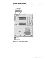
PWR1 PWR2 PWR3 FD HD_B/P To POWER1 connector on system board To POWER2 connector on system board Not used To diskette drives and other devices in external drive bays To POWER connector on SCSI backplane board The power-supply output voltages can be measured at the back (wire side) of the connectors without being disconnected. In the following diagrams, voltages for the PSPB PWRx connectors are shown as measured at the system board; voltages for the PSPB FD connector are shown as measured at the PSPB; voltages for the PSPB HD_B/P connector are shown as measured at the SCSI backplane. +5 VDC (red) -5 VDC (white) +5 VDC (red) +5 VDC (red) common (black) common (black) NC_TFSC (gray) +5 VDC (red) common (black) SYS_PS_ON #1 (gray) +3.3 VDC (orange) common (black) 13 14 15 16 17 18 19 20 21 22 23 24 1 2 3 4 5 6 7 8 9 10 11 12 +5 VDC (red) +3.3 VDC (orange) common (black) +3.3 V_SENSE (orange) +5 V_SENSE (red) SENSE (black) SYS_PWR_GOOD2 (gray) +5 VFP (violet) common (black) common (black) -12 VDC (blue) +12 VDC (yellow) 1 Pin 13 - SYS_PS_ON# should measure between +4.75 and +5.25 VDC except when the power button on the front panel is pressed, taking SYS_PS_ON# to its active-low state. 2 Pin 5 - SYS_PWR_GOOD should measure between +4.75 and +5.25 VDC when the power supply is operating to indicate that all power-supply output voltages are within the ranges specified in Table 1-1. 1-12 Dell PowerEdge 4300 Systems Service Manual
-
 1
1 -
2
-
3
-
4
-
5
-
6
-
7
-
8
-
9
-
10
-
11
-
12
-
13
-
14
-
 15
15 -
 16
16 -
 17
17 -
 18
18 -
 19
19 -
 20
20 -
 21
21 -
 22
22 -
 23
23 -
 24
24 -
 25
25 -
26
-
27
-
28
-
29
-
30
-
31
-
32
-
33
-
34
-
35
-
36
-
37
-
38
-
39
-
40
-
41
-
42
-
43
-
44
-
45
-
46
-
47
-
48
-
49
-
50
-
51
-
52
-
53
-
54
-
55
-
56
-
57
-
58
-
59
-
60
-
61
-
62
-
63
-
64
-
65
-
66
-
67
-
68
-
69
-
70
-
71
-
72
-
73
-
74
-
75
-
76
-
77
-
78
-
79
-
80
-
81
-
82
-
83
-
84
-
85
-
86
-
87
-
88
-
89
-
90
-
91
-
92
-
93
-
94
-
95
-
96
-
97
-
98
-
99
-
100
-
101
-
102
-
103
-
104
 |
 |
