Dell PowerEdge 4300 Dell PowerEdge 4300 Systems Service Manual - Page 87
Loosen the thumbscrews on the left side of the panel see
 |
View all Dell PowerEdge 4300 manuals
Add to My Manuals
Save this manual to your list of manuals |
Page 87 highlights
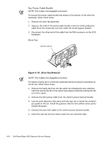
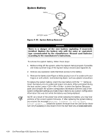
screws (2) support panel To access the microprocessors or the memory module, you must remove the interior support panel as follows: 1. Loosen the thumbscrews on the left side of the panel (see Figure 4-24). 2. Rotate the panel outward slightly, and lift the hinge side of the panel to clear the tabs from the hinge slot. Removing and Replacing Parts 4-29
-
 1
1 -
2
-
3
-
4
-
5
-
6
-
7
-
8
-
9
-
10
-
11
-
12
-
13
-
14
-
15
-
16
-
17
-
18
-
19
-
20
-
21
-
22
-
23
-
24
-
25
-
26
-
27
-
28
-
29
-
30
-
31
-
32
-
33
-
34
-
35
-
36
-
37
-
38
-
39
-
40
-
41
-
42
-
43
-
44
-
45
-
46
-
47
-
48
-
49
-
50
-
51
-
52
-
53
-
54
-
55
-
56
-
57
-
58
-
59
-
60
-
61
-
62
-
63
-
64
-
65
-
66
-
67
-
68
-
69
-
70
-
71
-
72
-
73
-
74
-
75
-
76
-
77
-
78
-
79
-
80
-
81
-
 82
82 -
 83
83 -
 84
84 -
 85
85 -
 86
86 -
 87
87 -
 88
88 -
 89
89 -
 90
90 -
 91
91 -
 92
92 -
93
-
94
-
95
-
96
-
97
-
98
-
99
-
100
-
101
-
102
-
103
-
104
 |
 |

Removing and Replacing Parts
4-29
,QWHULRU±6XSSRUW±3DQHO
)LJXUH±·´µ·³±±,QWHULRU±6XSSRUW±3DQHO±5HPRYDO
To access the microprocessors or the memory module, you must remove the
interior support panel as follows:
1.
Loosen the thumbscrews on the left side of the panel (see Figure 4-24).
2.
Rotate the panel outward slightly, and lift the hinge side of the panel to
clear the tabs from the hinge slot.
screws (2)
support panel