Dell PowerEdge 4300 Dell PowerEdge 4300 Systems Service Manual - Page 83
attached to the appropriate fan connector FAN1 or FAN2 on the system
 |
View all Dell PowerEdge 4300 manuals
Add to My Manuals
Save this manual to your list of manuals |
Page 83 highlights
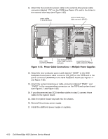
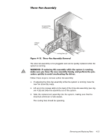
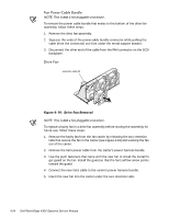
retention tabs (2) The system board fans are hot-pluggable and can be quickly replaced while the system is running. 1. Assemble the new fan. Use the push fasteners that came with the new fan to install the finger guard on the fan. Install the guard so that the fan's airflow arrow points away from the guard. 2. Slide the system board tray out to the service position. See "Accessing the Interior of the System" in Chapter 1 for instructions. 3. On the fan to be replaced, disconnect the cable from the extension cable attached to the appropriate fan connector (FAN1 or FAN2) on the system board. 4. Pull outward on the fan-retention tabs to disengage the fan (see Figure 4-20). To install the new fan, slide the fan into the fan housing, align the holes in the corners of the fan with the studs in the housing, and snap the fan into place. Connect the fan to the appropriate extension cable. Removing and Replacing Parts 4-25
-
 1
1 -
2
-
3
-
4
-
5
-
6
-
7
-
8
-
9
-
10
-
11
-
12
-
13
-
14
-
15
-
16
-
17
-
18
-
19
-
20
-
21
-
22
-
23
-
24
-
25
-
26
-
27
-
28
-
29
-
30
-
31
-
32
-
33
-
34
-
35
-
36
-
37
-
38
-
39
-
40
-
41
-
42
-
43
-
44
-
45
-
46
-
47
-
48
-
49
-
50
-
51
-
52
-
53
-
54
-
55
-
56
-
57
-
58
-
59
-
60
-
61
-
62
-
63
-
64
-
65
-
66
-
67
-
68
-
69
-
70
-
71
-
72
-
73
-
74
-
75
-
76
-
77
-
 78
78 -
 79
79 -
 80
80 -
 81
81 -
 82
82 -
 83
83 -
 84
84 -
 85
85 -
 86
86 -
 87
87 -
 88
88 -
89
-
90
-
91
-
92
-
93
-
94
-
95
-
96
-
97
-
98
-
99
-
100
-
101
-
102
-
103
-
104
 |
 |
