Dell PowerEdge 4300 Dell PowerEdge 4300 Systems Service Manual - Page 95
Loosen the four captive nuts that secure the guide bracket assembly to
 |
View all Dell PowerEdge 4300 manuals
Add to My Manuals
Save this manual to your list of manuals |
Page 95 highlights
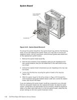
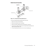
guide bracket assembly threaded posts (4) captive nuts (4) To remove the guide bracket assembly, follow these steps: 1. Remove the system board assembly. 2. Remove any terminator card, if necessary. 3. Remove any SEC cartridge and heat sink assembly, if necessary. 4. Loosen the four captive nuts that secure the guide bracket assembly to the system board (see Figure 4-33). 5. Lift up the assembly and remove it from the four threaded posts. Removing and Replacing Parts 4-37
-
 1
1 -
2
-
3
-
4
-
5
-
6
-
7
-
8
-
9
-
10
-
11
-
12
-
13
-
14
-
15
-
16
-
17
-
18
-
19
-
20
-
21
-
22
-
23
-
24
-
25
-
26
-
27
-
28
-
29
-
30
-
31
-
32
-
33
-
34
-
35
-
36
-
37
-
38
-
39
-
40
-
41
-
42
-
43
-
44
-
45
-
46
-
47
-
48
-
49
-
50
-
51
-
52
-
53
-
54
-
55
-
56
-
57
-
58
-
59
-
60
-
61
-
62
-
63
-
64
-
65
-
66
-
67
-
68
-
69
-
70
-
71
-
72
-
73
-
74
-
75
-
76
-
77
-
78
-
79
-
80
-
81
-
82
-
83
-
84
-
85
-
86
-
87
-
88
-
89
-
 90
90 -
 91
91 -
 92
92 -
 93
93 -
 94
94 -
 95
95 -
 96
96 -
 97
97 -
 98
98 -
 99
99 -
 100
100 -
101
-
102
-
103
-
104
 |
 |

Removing and Replacing Parts
4-37
*XLGH±%UDFNHW±$VVHPEO\
)LJXUH±·´¶¶³±±*XLGH´%UDFNHW±$VVHPEO\±5HPRYDO±±±
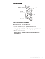
To remove the guide bracket assembly, follow these steps:
1.
Remove the system board assembly.
2.
Remove any terminator card, if necessary.
3.
Remove any SEC cartridge and heat sink assembly, if necessary.
4.
Loosen the four captive nuts that secure the guide bracket assembly to the
system board (see Figure 4-33).
5.
Lift up the assembly and remove it from the four threaded posts.
guide bracket
assembly
captive nuts (4)
threaded posts (4)