Dell PowerEdge 4300 Dell PowerEdge 4300 Systems Service Manual - Page 5
Ljxuhv
 |
View all Dell PowerEdge 4300 manuals
Add to My Manuals
Save this manual to your list of manuals |
Page 5 highlights
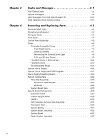
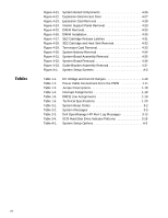
System Setup Screens A-2 Figure 1-1. Figure 1-2. Figure 1-3. Figure 1-4. Figure 1-5. Figure 1-6. Figure 1-7. Figure 1-8. Figure 1-9. Figure 1-10. Figure 1-11. Figure 1-12. Figure 1-13. Figure 1-14. Figure 1-15. Figure 3-1. Figure 4-1. Figure 4-2. Figure 4-3. Figure 4-4. Figure 4-5. Figure 4-6. Figure 4-7. Figure 4-8. Figure 4-9. Figure 4-10. Figure 4-11. Figure 4-12. Figure 4-13. Figure 4-14. Figure 4-15. Figure 4-16. Figure 4-17. Figure 4-18. Figure 4-19. Figure 4-20. Computer Orientation 1-3 Front-Panel Features 1-4 Back-Panel Features 1-4 Back/Right Side Internal View 1-5 Opening the System Board Tray 1-6 DIMM Sockets 1-7 Power-Supply Paralleling Board 1-11 PSPB Power Connector PWR1 1-12 PSPB Power Connector PWR2 1-13 PSPB Power Connector PWR3 1-13 PSPB Power Connector FD 1-13 PSPB Power Connector HD_B/P 1-14 System Board Components 1-15 SCSI Backplane Board 1-16 System Board Jumpers 1-17 Hard-Disk Drive Indicators 3-17 Computer Cover Removal 4-3 Front Bezel Removal 4-4 Control-Panel Assembly Removal 4-5 Drive Hardware 4-6 Front-Panel Inserts 4-7 Externally Accessible Drive Removal 4-9 Drive-Mounting Rail Removal (Example 4-10 Hard-Disk Drives in External Bay 4-11 Hard-Disk Drive Removal 4-12 SCSI Backplane Board Removal 4-14 Power Supply Removal 4-16 Power Cable Connections - Single Power Supply 4-17 PSPB Tray Location in the System Chassis 4-18 PSPB Installation on the PSPB Tray 4-19 Power Cable Connections - Multiple Power Supplies . . . 4-20 Power-Supply Paralleling Board Removal 4-21 System Cooling Fans 4-22 Three-Fan Assembly Removal 4-23 Drive Fan Removal 4-24 System-Board Fan Removal 4-25 vii
-
 1
1 -
 2
2 -
 3
3 -
 4
4 -
 5
5 -
 6
6 -
 7
7 -
 8
8 -
 9
9 -
 10
10 -
 11
11 -
12
-
13
-
14
-
15
-
16
-
17
-
18
-
19
-
20
-
21
-
22
-
23
-
24
-
25
-
26
-
27
-
28
-
29
-
30
-
31
-
32
-
33
-
34
-
35
-
36
-
37
-
38
-
39
-
40
-
41
-
42
-
43
-
44
-
45
-
46
-
47
-
48
-
49
-
50
-
51
-
52
-
53
-
54
-
55
-
56
-
57
-
58
-
59
-
60
-
61
-
62
-
63
-
64
-
65
-
66
-
67
-
68
-
69
-
70
-
71
-
72
-
73
-
74
-
75
-
76
-
77
-
78
-
79
-
80
-
81
-
82
-
83
-
84
-
85
-
86
-
87
-
88
-
89
-
90
-
91
-
92
-
93
-
94
-
95
-
96
-
97
-
98
-
99
-
100
-
101
-
102
-
103
-
104
 |
 |
