Dell PowerEdge 4300 Dell PowerEdge 4300 Systems Service Manual - Page 23
board components.
 |
View all Dell PowerEdge 4300 manuals
Add to My Manuals
Save this manual to your list of manuals |
Page 23 highlights
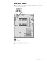
Figure 1-13 illustrates the location of important system board components. The subsections that follow provide service-related information about the system board components. SCSI backplane board interface connector (BACKPLANE) chassis-intrusion switch connector (INTRUS2) diskette-drive interface connector (FLOPPY) Ultra/Narrow SCSI connector (SCSI2) Ultra2/LVD SCSI connector (SCSI1) fan connectors (FAN1, FAN2) hard-disk drive activity indicator connector (HLED) secondary microprocessor (PROCESSOR 2) Dell Remote Assistant Card connector (SVR_MGT) front of system board speed and configuration jumpers power input connector (POWER1) power input connector (POWER2) system-board power indicator (STANDBY_LED) primary microprocessor (PROCESSOR 1) DIMM sockets (DIMM_A [right]-DIMM_D) keyboard and mouse connectors (KYBD/MOUSE) server management bus connector (XSMB_OUT) server management bus connector (XSMB_IN) serial port connectors (2) (SERIAL1 [top] and SERIAL2) parallel port connector (PARALLEL) video connector (JVGA) storage-system server-management bus connector (SDS_SMB) battery connector (BATTERY) primary PCI connectors (PCI1 [top] through PCI4) ISA connectors (ISA5 [top] and ISA6) secondary PCI connectors (PCI5 [top] and PCI6) System Overview 1-15
-
 1
1 -
2
-
3
-
4
-
5
-
6
-
7
-
8
-
9
-
10
-
11
-
12
-
13
-
14
-
15
-
16
-
17
-
 18
18 -
 19
19 -
 20
20 -
 21
21 -
 22
22 -
 23
23 -
 24
24 -
 25
25 -
 26
26 -
 27
27 -
 28
28 -
29
-
30
-
31
-
32
-
33
-
34
-
35
-
36
-
37
-
38
-
39
-
40
-
41
-
42
-
43
-
44
-
45
-
46
-
47
-
48
-
49
-
50
-
51
-
52
-
53
-
54
-
55
-
56
-
57
-
58
-
59
-
60
-
61
-
62
-
63
-
64
-
65
-
66
-
67
-
68
-
69
-
70
-
71
-
72
-
73
-
74
-
75
-
76
-
77
-
78
-
79
-
80
-
81
-
82
-
83
-
84
-
85
-
86
-
87
-
88
-
89
-
90
-
91
-
92
-
93
-
94
-
95
-
96
-
97
-
98
-
99
-
100
-
101
-
102
-
103
-
104
 |
 |
