Dell PowerEdge 4300 Dell PowerEdge 4300 Systems Service Manual - Page 90
NOTE: Do, attempt to operate the system with the microprocessor set to a, speed other than
 |
View all Dell PowerEdge 4300 manuals
Add to My Manuals
Save this manual to your list of manuals |
Page 90 highlights
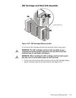
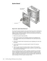
2. Remove the two retention pins from the SEC cartridge and heat sink assembly (see Figure 4-28). retention pins (2) SEC cartridge SEC cartridge release latches (2) heat sink guide bracket assembly 3. Pull the SEC cartridge straight up out of the connector and guide bracket assembly (some force may be required). To replace an SEC cartridge, make sure the cartridge release latches are in the open position, orient the new SEC cartridge in the guide bracket assembly (as shown in Figure 4-28) and seat it firmly, and then snap the release latches back into place. Reinstall the two retention pins. To install an SEC cartridge where there was none before, you will need to remove the installed terminator card (see the next subsection, "Terminator Card"). NOTE: Do not attempt to operate the system with the microprocessor set to a speed other than the specified rating. 4-32 Dell PowerEdge 4300 Systems Service Manual
-
 1
1 -
2
-
3
-
4
-
5
-
6
-
7
-
8
-
9
-
10
-
11
-
12
-
13
-
14
-
15
-
16
-
17
-
18
-
19
-
20
-
21
-
22
-
23
-
24
-
25
-
26
-
27
-
28
-
29
-
30
-
31
-
32
-
33
-
34
-
35
-
36
-
37
-
38
-
39
-
40
-
41
-
42
-
43
-
44
-
45
-
46
-
47
-
48
-
49
-
50
-
51
-
52
-
53
-
54
-
55
-
56
-
57
-
58
-
59
-
60
-
61
-
62
-
63
-
64
-
65
-
66
-
67
-
68
-
69
-
70
-
71
-
72
-
73
-
74
-
75
-
76
-
77
-
78
-
79
-
80
-
81
-
82
-
83
-
84
-
 85
85 -
 86
86 -
 87
87 -
 88
88 -
 89
89 -
 90
90 -
 91
91 -
 92
92 -
 93
93 -
 94
94 -
 95
95 -
96
-
97
-
98
-
99
-
100
-
101
-
102
-
103
-
104
 |
 |
