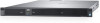
Dell PowerEdge C4140 EMC Installation and Service Manual - Page 103
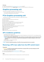
Removing the GPU switch board
 |
View all Dell PowerEdge C4140 manuals
Add to My Manuals
Save this manual to your list of manuals |
Page 103 highlights
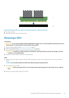
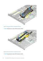
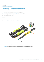
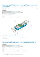
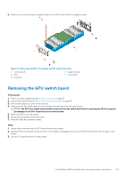
2. Remove the screws securing the support bracket to the GPU, and remove the support bracket. Figure 71. Removing the GPU I/O brackets and the support brackets 1. Torx screw (2) 3. GPU 5. screw (5) 2. support bracket 4. I/O bracket Removing the GPU switch board Prerequisites 1. Follow the safety guidelines listed in Safety instructions on page 57. 2. Follow the procedure listed in Before working inside your system on page 58. 3. Remove the system top cover (front and rear). 4. Disconnect the GPU signal cables from the system board and then from the switch board. NOTE: The GPU riser signal cable should be removed from the switch board before removing the GPUs to prevent pin damage in the GPU connectors on the switch board. 5. Remove all GPUs from the chassis. 6. Disconnect the switch board power cable. 7. Keep the Philips #2 screwdriver ready. Steps 1. Loosen the screws securing the GPU switch board to the chassis. 2. Slide the GPU switch board toward the front of the chassis to disengage the slots on the GPU switch board from the tabs on the chassis. 3. Lift the GPU switch board out of the chassis. PowerEdge C4140 installing and removing system components 103
-
 1
1 -
2
-
3
-
4
-
5
-
6
-
7
-
8
-
9
-
10
-
11
-
12
-
13
-
14
-
15
-
16
-
17
-
18
-
19
-
20
-
21
-
22
-
23
-
24
-
25
-
26
-
27
-
28
-
29
-
30
-
31
-
32
-
33
-
34
-
35
-
36
-
37
-
38
-
39
-
40
-
41
-
42
-
43
-
44
-
45
-
46
-
47
-
48
-
49
-
50
-
51
-
52
-
53
-
54
-
55
-
56
-
57
-
58
-
59
-
60
-
61
-
62
-
63
-
64
-
65
-
66
-
67
-
68
-
69
-
70
-
71
-
72
-
73
-
74
-
75
-
76
-
77
-
78
-
79
-
80
-
81
-
82
-
83
-
84
-
85
-
86
-
87
-
88
-
89
-
90
-
91
-
92
-
93
-
94
-
95
-
96
-
97
-
 98
98 -
 99
99 -
 100
100 -
 101
101 -
 102
102 -
 103
103 -
 104
104 -
 105
105 -
 106
106 -
 107
107 -
 108
108 -
109
-
110
-
111
-
112
-
113
-
114
-
115
-
116
-
117
-
118
-
119
-
120
-
121
-
122
-
123
-
124
-
125
-
126
-
127
-
128
-
129
-
130
-
131
-
132
-
133
-
134
-
135
-
136
-
137
-
138
-
139
-
140
-
141
 |
 |
