Dell PowerEdge C4140 EMC Installation and Service Manual - Page 98
Graphics processing unit, GPU installation guidelines
 |
View all Dell PowerEdge C4140 manuals
Add to My Manuals
Save this manual to your list of manuals |
Page 98 highlights
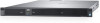
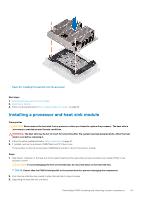
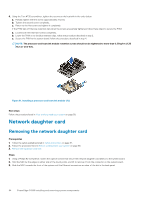
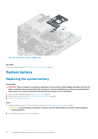
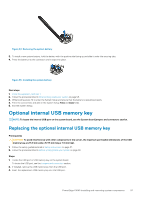
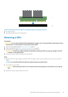
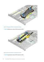
Next steps 1. Follow the procedure listed in After working inside your system on page 58. 2. While booting, press F2 to enter System Setup and verify that the system detects the USB memory key. Graphics processing unit The Dell EMC PowerEdge C4140 supports two form factors of GPUs: • Four PCIe GPUs supported with the GPU switch board or system board. • Four SXM2 GPUs supported with the NVLink board. PCIe Graphics processing unit The following are the high-level steps that you must perform to replace the PCIe GPUs: 1. Remove the GPU blank. 2. Remove the GPU riser cable from the system board. 3. Remove the GPU. 4. Remove the GPU riser cable board. 5. Remove the GPU brackets from the GPU removed from your system. 6. Remove the custom GPU brackets from the replacement GPU. 7. Remove the optional GPU switch board. 8. Install the optional GPU switch board. 9. Install the custom GPU brackets on the GPU removed from your system. 10. Install the GPU brackets on the replacement GPU. 11. Install the GPU riser cable board. 12. Install the GPU blank. 13. Install the GPU. 14. Install the GPU riser cable on the system board. GPU installation guidelines • The processor must be of 150 W or less. • Due to the high power consumption of GPUs, the ambient system inlet temperature is restricted to 25°C to ensure adequate system cooling when one or more GPU cards are installed. NOTE: Certain system configurations may require reduction in the maximum ambient system inlet temperature limit. The performance of the system may be impacted when operating above the maximum temperature limit or with a faulty fan. • All GPUs must be of the same type and model. • You can install up to four GPUs. NOTE: Incorrect removal and installation of the GPUs will cause operational issues to your system. Removing a GPU riser cable from the GPU switch board Prerequisites CAUTION: The GPU riser cables should be removed before removing the GPUs to prevent pin damage in the GPU connectors on the GPU switch board. 1. Follow the safety guidelines listed in Safety instructions on page 57. 2. Follow the procedure listed in Before working inside your system on page 58. Steps Disconnect the GPU riser cable from the GPU riser cable connector on the GPU switch board. 98 PowerEdge C4140 installing and removing system components
-
 1
1 -
2
-
3
-
4
-
5
-
6
-
7
-
8
-
9
-
10
-
11
-
12
-
13
-
14
-
15
-
16
-
17
-
18
-
19
-
20
-
21
-
22
-
23
-
24
-
25
-
26
-
27
-
28
-
29
-
30
-
31
-
32
-
33
-
34
-
35
-
36
-
37
-
38
-
39
-
40
-
41
-
42
-
43
-
44
-
45
-
46
-
47
-
48
-
49
-
50
-
51
-
52
-
53
-
54
-
55
-
56
-
57
-
58
-
59
-
60
-
61
-
62
-
63
-
64
-
65
-
66
-
67
-
68
-
69
-
70
-
71
-
72
-
73
-
74
-
75
-
76
-
77
-
78
-
79
-
80
-
81
-
82
-
83
-
84
-
85
-
86
-
87
-
88
-
89
-
90
-
91
-
92
-
 93
93 -
 94
94 -
 95
95 -
 96
96 -
 97
97 -
 98
98 -
 99
99 -
 100
100 -
 101
101 -
 102
102 -
 103
103 -
104
-
105
-
106
-
107
-
108
-
109
-
110
-
111
-
112
-
113
-
114
-
115
-
116
-
117
-
118
-
119
-
120
-
121
-
122
-
123
-
124
-
125
-
126
-
127
-
128
-
129
-
130
-
131
-
132
-
133
-
134
-
135
-
136
-
137
-
138
-
139
-
140
-
141
 |
 |