Dell PowerEdge C4140 EMC Installation and Service Manual - Page 94
Network daughter card, Removing the network daughter card
 |
View all Dell PowerEdge C4140 manuals
Add to My Manuals
Save this manual to your list of manuals |
Page 94 highlights
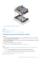
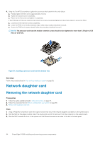
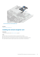
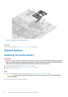
4. Using the Torx #T30 screwdriver, tighten the screws on the heat sink in the order below: a. Partially tighten the first screw (approximately 3 turns). b. Tighten the second screw completely. c. Return to the first screw and tighten it completely. If the PHM slips off the blue retention clips when the screws are partially tightened, follow these steps to secure the PHM: a. Loosen both the heat sink screws completely. b. Lower the PHM on to the blue retention clips, follow the procedure described in step 2. c. Secure the PHM to the system board, follow the procedure described in step 4. NOTE: The processor and heat sink module retention screws should not be tightened to more than 0.13 kgf-m (1.35 N.m or 12 in-lbf). Figure 61. Installing a processor and heat sink module (1U) Next steps Follow the procedure listed in After working inside your system on page 58. Network daughter card Removing the network daughter card Prerequisites 1. Follow the safety guidelines listed in Safety instructions on page 57. 2. Follow the procedure listed in Before working inside your system on page 58. 3. Remove the expansion card riser. Steps 1. Using a Phillips #2 screwdriver, loosen the captive screws that secure the network daughter card (NDC) to the system board. 2. Hold the NDC by the edges on either side of the touch points, and lift to remove it from the connector on the system board. 3. Slide the NDC towards the front of the system until the Ethernet connectors are clear of the slot in the back panel. 94 PowerEdge C4140 installing and removing system components
-
 1
1 -
2
-
3
-
4
-
5
-
6
-
7
-
8
-
9
-
10
-
11
-
12
-
13
-
14
-
15
-
16
-
17
-
18
-
19
-
20
-
21
-
22
-
23
-
24
-
25
-
26
-
27
-
28
-
29
-
30
-
31
-
32
-
33
-
34
-
35
-
36
-
37
-
38
-
39
-
40
-
41
-
42
-
43
-
44
-
45
-
46
-
47
-
48
-
49
-
50
-
51
-
52
-
53
-
54
-
55
-
56
-
57
-
58
-
59
-
60
-
61
-
62
-
63
-
64
-
65
-
66
-
67
-
68
-
69
-
70
-
71
-
72
-
73
-
74
-
75
-
76
-
77
-
78
-
79
-
80
-
81
-
82
-
83
-
84
-
85
-
86
-
87
-
88
-
 89
89 -
 90
90 -
 91
91 -
 92
92 -
 93
93 -
 94
94 -
 95
95 -
 96
96 -
 97
97 -
 98
98 -
 99
99 -
100
-
101
-
102
-
103
-
104
-
105
-
106
-
107
-
108
-
109
-
110
-
111
-
112
-
113
-
114
-
115
-
116
-
117
-
118
-
119
-
120
-
121
-
122
-
123
-
124
-
125
-
126
-
127
-
128
-
129
-
130
-
131
-
132
-
133
-
134
-
135
-
136
-
137
-
138
-
139
-
140
-
141
 |
 |
