Dell PowerEdge R750 EMC Installation and Service Manual - Page 102
Processor and heat sink module, Removing the processor and heat sink module
 |
View all Dell PowerEdge R750 manuals
Add to My Manuals
Save this manual to your list of manuals |
Page 102 highlights
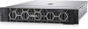
Processor and heat sink module Removing the processor and heat sink module Prerequisites 1. Follow the safety guidelines listed in the Safety instructions. 2. Follow the procedure listed in the Before working inside your system. 3. Remove the air shroud or remove the GPU air shroud. NOTE: The heat sink and processor are hot to touch for some time after the system has been powered down. Allow the heat sink and processor to cool down before handling them. Steps 1. Ensure all four anti-tilt wires are in the locked position (outward position), and then using a Torx #T30 screwdriver, loosen the captive screws on the processor heat sink module (PHM) in the order that is mentioned below: a. Loosen the first screw three turns. b. Loosen the screw diagonally opposite to the screw you loosened first. c. Repeat the procedure for the remaining two screws. d. Return to the first screw and loosen it completely. NOTE: Ensure that the anti-tilt wires on the PHM are in locked position when loosening the captive screws. 2. Set all the anti-tilt wires to unlocked position (inward position). Figure 99. Removing the processor heat sink module 3. Lift the PHM from the system and set the PHM aside with the processor side facing up. 102 Installing and removing system components
-
 1
1 -
2
-
3
-
4
-
5
-
6
-
7
-
8
-
9
-
10
-
11
-
12
-
13
-
14
-
15
-
16
-
17
-
18
-
19
-
20
-
21
-
22
-
23
-
24
-
25
-
26
-
27
-
28
-
29
-
30
-
31
-
32
-
33
-
34
-
35
-
36
-
37
-
38
-
39
-
40
-
41
-
42
-
43
-
44
-
45
-
46
-
47
-
48
-
49
-
50
-
51
-
52
-
53
-
54
-
55
-
56
-
57
-
58
-
59
-
60
-
61
-
62
-
63
-
64
-
65
-
66
-
67
-
68
-
69
-
70
-
71
-
72
-
73
-
74
-
75
-
76
-
77
-
78
-
79
-
80
-
81
-
82
-
83
-
84
-
85
-
86
-
87
-
88
-
89
-
90
-
91
-
92
-
93
-
94
-
95
-
96
-
 97
97 -
 98
98 -
 99
99 -
 100
100 -
 101
101 -
 102
102 -
 103
103 -
 104
104 -
 105
105 -
 106
106 -
 107
107 -
108
-
109
-
110
-
111
-
112
-
113
-
114
-
115
-
116
-
117
-
118
-
119
-
120
-
121
-
122
-
123
-
124
-
125
-
126
-
127
-
128
-
129
-
130
-
131
-
132
-
133
-
134
-
135
-
136
-
137
-
138
-
139
-
140
-
141
-
142
-
143
-
144
-
145
-
146
-
147
-
148
-
149
-
150
-
151
-
152
-
153
-
154
-
155
-
156
-
157
-
158
-
159
-
160
-
161
-
162
-
163
-
164
-
165
-
166
-
167
-
168
-
169
-
170
-
171
-
172
-
173
-
174
-
175
-
176
-
177
-
178
-
179
-
180
-
181
-
182
-
183
-
184
-
185
-
186
-
187
-
188
-
189
-
190
-
191
-
192
-
193
-
194
-
195
-
196
-
197
-
198
-
199
-
200
-
201
-
202
-
203
-
204
-
205
-
206
-
207
-
208
-
209
-
210
-
211
-
212
-
213
-
214
-
215
-
216
-
217
-
218
-
219
-
220
-
221
-
222
-
223
-
224
-
225
-
226
-
227
-
228
-
229
-
230
-
231
 |
 |
