Dell PowerEdge R750 EMC Installation and Service Manual - Page 66
Removing the drive backplane, x 2.5-inch drive backplane
 |
View all Dell PowerEdge R750 manuals
Add to My Manuals
Save this manual to your list of manuals |
Page 66 highlights
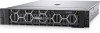
Figure 62. 24 x 2.5-inch drive backplane 1. DST_SA1 3. DST_SB1 5. BP_DST_PA1 (PCIe/NVMe connector) 7. BP_ DST_PB1 (PCIe/NVMe connector) 9. BP_ DST_PA2 (PCIe/NVMe connector) 2. SRC_SA1 4. BP_PWR_1 6. BP_PWR_2 8. BP_PWR_CTRL 10. BP_ DST_PB2 (PCIe/NVMe connector) Removing the drive backplane Prerequisites CAUTION: To prevent damage to the drives and backplane, remove the drives from the system before removing the backplane. CAUTION: Note the number of each drive and temporarily label them before you remove the drive so that you can reinstall them in the same location. NOTE: The procedure to remove the backplane is similar for all backplane configurations. 1. Follow the safety guidelines listed in the Safety instructions. 2. Follow the procedure listed in the Before working inside your system. 3. Remove the backplane cover. 4. If installed, remove the air shroud or remove the GPU air shroud. 5. Remove the cooling fan cage assembly. 6. Remove the drives. 7. Observe and disconnect the drive backplane cables from the connector on the system board and backplane. Steps 1. Press the blue release tabs to disengage the drive backplane from the hooks on the system. 2. Lift and pull the drive backplane out of the system. NOTE: To avoid damaging the backplane, ensure that you move the control panel cables from the cable routing clips before removing the backplane. 66 Installing and removing system components
-
 1
1 -
2
-
3
-
4
-
5
-
6
-
7
-
8
-
9
-
10
-
11
-
12
-
13
-
14
-
15
-
16
-
17
-
18
-
19
-
20
-
21
-
22
-
23
-
24
-
25
-
26
-
27
-
28
-
29
-
30
-
31
-
32
-
33
-
34
-
35
-
36
-
37
-
38
-
39
-
40
-
41
-
42
-
43
-
44
-
45
-
46
-
47
-
48
-
49
-
50
-
51
-
52
-
53
-
54
-
55
-
56
-
57
-
58
-
59
-
60
-
 61
61 -
 62
62 -
 63
63 -
 64
64 -
 65
65 -
 66
66 -
 67
67 -
 68
68 -
 69
69 -
 70
70 -
 71
71 -
72
-
73
-
74
-
75
-
76
-
77
-
78
-
79
-
80
-
81
-
82
-
83
-
84
-
85
-
86
-
87
-
88
-
89
-
90
-
91
-
92
-
93
-
94
-
95
-
96
-
97
-
98
-
99
-
100
-
101
-
102
-
103
-
104
-
105
-
106
-
107
-
108
-
109
-
110
-
111
-
112
-
113
-
114
-
115
-
116
-
117
-
118
-
119
-
120
-
121
-
122
-
123
-
124
-
125
-
126
-
127
-
128
-
129
-
130
-
131
-
132
-
133
-
134
-
135
-
136
-
137
-
138
-
139
-
140
-
141
-
142
-
143
-
144
-
145
-
146
-
147
-
148
-
149
-
150
-
151
-
152
-
153
-
154
-
155
-
156
-
157
-
158
-
159
-
160
-
161
-
162
-
163
-
164
-
165
-
166
-
167
-
168
-
169
-
170
-
171
-
172
-
173
-
174
-
175
-
176
-
177
-
178
-
179
-
180
-
181
-
182
-
183
-
184
-
185
-
186
-
187
-
188
-
189
-
190
-
191
-
192
-
193
-
194
-
195
-
196
-
197
-
198
-
199
-
200
-
201
-
202
-
203
-
204
-
205
-
206
-
207
-
208
-
209
-
210
-
211
-
212
-
213
-
214
-
215
-
216
-
217
-
218
-
219
-
220
-
221
-
222
-
223
-
224
-
225
-
226
-
227
-
228
-
229
-
230
-
231
 |
 |
