Dell PowerEdge R750 EMC Installation and Service Manual - Page 19
Locating the Express Service Code and Service Tag
 |
View all Dell PowerEdge R750 manuals
Add to My Manuals
Save this manual to your list of manuals |
Page 19 highlights
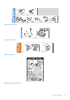
Figure 13. Inside the system with liquid cooling module 1. Handle 3. Riser 2 5. Memory DIMM sockets 7. Cooling fan 9. Service tag 11. Power supply unit (PSU 2) 13. Liquid cooling module tubes 2. Power supply unit (PSU 1) 4. System board 6. Liquid cooling module 8. Drive backplane 10. Cooling fan cage assembly 12. Intrusion switch module NOTE: To show the liquid cooling configuration system, air shroud is not shown in the image. Locating the Express Service Code and Service Tag The unique Express Service Code and Service Tag are used to identify the system. System overview 19
-
 1
1 -
2
-
3
-
4
-
5
-
6
-
7
-
8
-
9
-
10
-
11
-
12
-
13
-
 14
14 -
 15
15 -
 16
16 -
 17
17 -
 18
18 -
 19
19 -
 20
20 -
 21
21 -
 22
22 -
 23
23 -
 24
24 -
25
-
26
-
27
-
28
-
29
-
30
-
31
-
32
-
33
-
34
-
35
-
36
-
37
-
38
-
39
-
40
-
41
-
42
-
43
-
44
-
45
-
46
-
47
-
48
-
49
-
50
-
51
-
52
-
53
-
54
-
55
-
56
-
57
-
58
-
59
-
60
-
61
-
62
-
63
-
64
-
65
-
66
-
67
-
68
-
69
-
70
-
71
-
72
-
73
-
74
-
75
-
76
-
77
-
78
-
79
-
80
-
81
-
82
-
83
-
84
-
85
-
86
-
87
-
88
-
89
-
90
-
91
-
92
-
93
-
94
-
95
-
96
-
97
-
98
-
99
-
100
-
101
-
102
-
103
-
104
-
105
-
106
-
107
-
108
-
109
-
110
-
111
-
112
-
113
-
114
-
115
-
116
-
117
-
118
-
119
-
120
-
121
-
122
-
123
-
124
-
125
-
126
-
127
-
128
-
129
-
130
-
131
-
132
-
133
-
134
-
135
-
136
-
137
-
138
-
139
-
140
-
141
-
142
-
143
-
144
-
145
-
146
-
147
-
148
-
149
-
150
-
151
-
152
-
153
-
154
-
155
-
156
-
157
-
158
-
159
-
160
-
161
-
162
-
163
-
164
-
165
-
166
-
167
-
168
-
169
-
170
-
171
-
172
-
173
-
174
-
175
-
176
-
177
-
178
-
179
-
180
-
181
-
182
-
183
-
184
-
185
-
186
-
187
-
188
-
189
-
190
-
191
-
192
-
193
-
194
-
195
-
196
-
197
-
198
-
199
-
200
-
201
-
202
-
203
-
204
-
205
-
206
-
207
-
208
-
209
-
210
-
211
-
212
-
213
-
214
-
215
-
216
-
217
-
218
-
219
-
220
-
221
-
222
-
223
-
224
-
225
-
226
-
227
-
228
-
229
-
230
-
231
 |
 |

Figure 13. Inside the system with liquid cooling module
1.
Handle
2.
Power supply unit (PSU 1)
3.
Riser 2
4.
System board
5.
Memory DIMM sockets
6.
Liquid cooling module
7.
Cooling fan
8.
Drive backplane
9.
Service tag
10. Cooling fan cage assembly
11.
Power supply unit (PSU 2)
12. Intrusion switch module
13. Liquid cooling module tubes
NOTE:
To show the liquid cooling configuration system, air shroud is not shown in the image.
Locating the Express Service Code and Service Tag
The unique Express Service Code and Service Tag are used to identify the system.
System overview
19