Dell PowerEdge R750 EMC Installation and Service Manual - Page 184
Intrusion switch module, Removing the intrusion switch module
 |
View all Dell PowerEdge R750 manuals
Add to My Manuals
Save this manual to your list of manuals |
Page 184 highlights
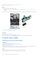
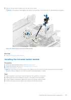
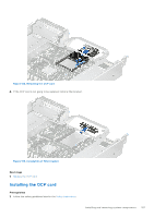
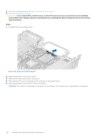
2. Follow the procedure listed in Before working inside your system. 3. Remove the expansion card risers. Steps 1. Connect the USB key to the internal USB card. NOTE: For information on the exact location of USB on system board, see System board jumpers and connectors section 2. Align the internal USB card with the connector on the system board and press firmly until the internal USB card is seated. Figure 190. Installing the internal USB card Next steps 1. Install the expansion card risers. 2. Follow the procedure listed in After working inside your system. 3. While booting, press F2 to enter System Setup and verify that the system detects the USB memory key. Intrusion switch module Removing the intrusion switch module Prerequisites 1. Follow the safety guidelines listed in the Safety instructions. 2. Follow the procedure listed in the Before working inside your system. 3. Remove the expansion card riser. NOTE: Ensure that you note the routing of the cables as you remove them from the system board. Route the cable properly when you replace it to prevent the cable from being pinched or crimped Steps 1. Disconnect the intrusion switch cable from the connector on the rear I/O board. 2. Using a Phillips #1 screwdriver, loosen the screw on the intrusion switch module. 184 Installing and removing system components
-
 1
1 -
2
-
3
-
4
-
5
-
6
-
7
-
8
-
9
-
10
-
11
-
12
-
13
-
14
-
15
-
16
-
17
-
18
-
19
-
20
-
21
-
22
-
23
-
24
-
25
-
26
-
27
-
28
-
29
-
30
-
31
-
32
-
33
-
34
-
35
-
36
-
37
-
38
-
39
-
40
-
41
-
42
-
43
-
44
-
45
-
46
-
47
-
48
-
49
-
50
-
51
-
52
-
53
-
54
-
55
-
56
-
57
-
58
-
59
-
60
-
61
-
62
-
63
-
64
-
65
-
66
-
67
-
68
-
69
-
70
-
71
-
72
-
73
-
74
-
75
-
76
-
77
-
78
-
79
-
80
-
81
-
82
-
83
-
84
-
85
-
86
-
87
-
88
-
89
-
90
-
91
-
92
-
93
-
94
-
95
-
96
-
97
-
98
-
99
-
100
-
101
-
102
-
103
-
104
-
105
-
106
-
107
-
108
-
109
-
110
-
111
-
112
-
113
-
114
-
115
-
116
-
117
-
118
-
119
-
120
-
121
-
122
-
123
-
124
-
125
-
126
-
127
-
128
-
129
-
130
-
131
-
132
-
133
-
134
-
135
-
136
-
137
-
138
-
139
-
140
-
141
-
142
-
143
-
144
-
145
-
146
-
147
-
148
-
149
-
150
-
151
-
152
-
153
-
154
-
155
-
156
-
157
-
158
-
159
-
160
-
161
-
162
-
163
-
164
-
165
-
166
-
167
-
168
-
169
-
170
-
171
-
172
-
173
-
174
-
175
-
176
-
177
-
178
-
 179
179 -
 180
180 -
 181
181 -
 182
182 -
 183
183 -
 184
184 -
 185
185 -
 186
186 -
 187
187 -
 188
188 -
 189
189 -
190
-
191
-
192
-
193
-
194
-
195
-
196
-
197
-
198
-
199
-
200
-
201
-
202
-
203
-
204
-
205
-
206
-
207
-
208
-
209
-
210
-
211
-
212
-
213
-
214
-
215
-
216
-
217
-
218
-
219
-
220
-
221
-
222
-
223
-
224
-
225
-
226
-
227
-
228
-
229
-
230
-
231
 |
 |
