Dell PowerEdge R750 EMC Installation and Service Manual - Page 198
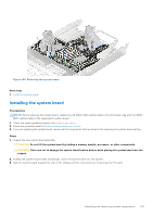
Installing the system board
 |
View all Dell PowerEdge R750 manuals
Add to My Manuals
Save this manual to your list of manuals |
Page 198 highlights
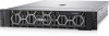
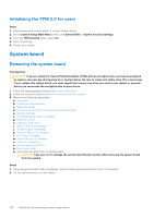
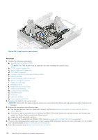
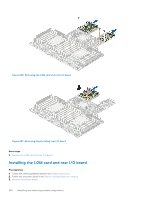
Figure 205. Installing the system board Next steps 1. Replace the following components: a. Trusted Platform Module (TPM) NOTE: The TPM Module must be replaced only while installing new system board. b. IDSDM module (if removed) c. Internal USB card (if removed) d. OCP card (if removed) e. Processor and heat sink or Liquid cooling module f. Memory modules g. R1 and R3 paddle cards (if removed) h. GPU air shroud (if removed) i. Expansion card risers j. BOSS S2 module k. Serial COM port (if removed) l. VGA port (if removed) m. Cooling fan cage assembly n. Side wall bracket o. Air shroud p. Rear drive module q. Power supply units (PSU) 2. Reconnect all cables to the system board. NOTE: Ensure that the cables inside the system are routed along the chassis wall and secured using the cable securing bracket. 3. Ensure that you perform the following steps: a. Use the Easy Restore feature to restore the Service Tag. See the Restoring the system by using the Easy Restore feature section. b. If the service tag is not backed up in the backup flash device, enter the system service tag manually. See the Manually update the Service Tag by using System Setup section. c. Update the BIOS and iDRAC versions. d. Re-enable the Trusted Platform Module (TPM). See the Upgrading the Trusted Platform Module section. 4. If you are not using Easy restore, import your new or existing iDRAC Enterprise license. For more information, see the iDRAC User's Guide available at https://www.dell.com/idracmanuals . 5. Follow the procedure listed in After working inside your system. 198 Installing and removing system components
-
 1
1 -
2
-
3
-
4
-
5
-
6
-
7
-
8
-
9
-
10
-
11
-
12
-
13
-
14
-
15
-
16
-
17
-
18
-
19
-
20
-
21
-
22
-
23
-
24
-
25
-
26
-
27
-
28
-
29
-
30
-
31
-
32
-
33
-
34
-
35
-
36
-
37
-
38
-
39
-
40
-
41
-
42
-
43
-
44
-
45
-
46
-
47
-
48
-
49
-
50
-
51
-
52
-
53
-
54
-
55
-
56
-
57
-
58
-
59
-
60
-
61
-
62
-
63
-
64
-
65
-
66
-
67
-
68
-
69
-
70
-
71
-
72
-
73
-
74
-
75
-
76
-
77
-
78
-
79
-
80
-
81
-
82
-
83
-
84
-
85
-
86
-
87
-
88
-
89
-
90
-
91
-
92
-
93
-
94
-
95
-
96
-
97
-
98
-
99
-
100
-
101
-
102
-
103
-
104
-
105
-
106
-
107
-
108
-
109
-
110
-
111
-
112
-
113
-
114
-
115
-
116
-
117
-
118
-
119
-
120
-
121
-
122
-
123
-
124
-
125
-
126
-
127
-
128
-
129
-
130
-
131
-
132
-
133
-
134
-
135
-
136
-
137
-
138
-
139
-
140
-
141
-
142
-
143
-
144
-
145
-
146
-
147
-
148
-
149
-
150
-
151
-
152
-
153
-
154
-
155
-
156
-
157
-
158
-
159
-
160
-
161
-
162
-
163
-
164
-
165
-
166
-
167
-
168
-
169
-
170
-
171
-
172
-
173
-
174
-
175
-
176
-
177
-
178
-
179
-
180
-
181
-
182
-
183
-
184
-
185
-
186
-
187
-
188
-
189
-
190
-
191
-
192
-
 193
193 -
 194
194 -
 195
195 -
 196
196 -
 197
197 -
 198
198 -
 199
199 -
 200
200 -
 201
201 -
 202
202 -
 203
203 -
204
-
205
-
206
-
207
-
208
-
209
-
210
-
211
-
212
-
213
-
214
-
215
-
216
-
217
-
218
-
219
-
220
-
221
-
222
-
223
-
224
-
225
-
226
-
227
-
228
-
229
-
230
-
231
 |
 |
