Dell PowerVault LTO4-120HH Dell DR Series System Administrator's Guide - Page 26
DR Series System and Data Operations, Dell DR, Series System Interoperability Guide
 |
View all Dell PowerVault LTO4-120HH manuals
Add to My Manuals
Save this manual to your list of manuals |
Page 26 highlights
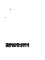
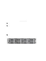
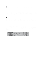
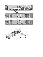
• Optimal supported aggregated throughput rates: - 3 Terabytes per hour (TB/hr) for passthrough write operations - 4 TB/hr for optimized write operations NOTE: Passthrough writes are when data is sent from a media server to the DR Series system without applying any optimization to the data. By contrast, optimized writes are when data is sent from a media server to the DR Series system after optimization is applied to the data. • Supported OST operations - Backup (Passthrough writes and Optimized writes) - Restore - Replication NOTE: To check for the latest supported OST software components and operating guidelines, see the Dell DR Series System Interoperability Guide. This document is available at support.dell.com/manuals. DR Series System and Data Operations Data is stored and resides on the Dell DR Series system, a two-rack unit (RU) appliance, which comes preinstalled with the system software. Starting with the 2.0 release. the DR Series system comes in two types: • DR4000 system: this consists of preinstalled DR4000 system software on a Dell R510 appliance platform. • DR4100 system: this consists of preinstalled DR4000 system software on a Dell R720xd appliance platform. The DR Series system consists of a total of 14 drives. Two of these drives are 2.5-inch drives that are configured as a Redundant Array of Independent Disks (RAID) 1 on the RAID Controller and this is considered to be volume 1. In the DR4000 system, these drives are internal, while in the DR4100 system, these drives are accessible from the rear. The data that is being backed up is stored on the 12 virtual disks that reside on the DR Series system appliance. This release also supported additional storage in the form of external expansion shelf enclosures (see the DR Series Expansion Shelf section in this topic). The hot-swappable data drives that are attached to the RAID controller are configured as: • 11 drives that operate as RAID 6, which act as virtual-disks for data storage (drives 1-11). • The remaining drive (drive 0) acts as the dedicated hot-spare drive for RAID 6 for the system. The DR Series system supports RAID 6, which allows the appliance to continue read and write requests to the RAID array virtual disks even in the event of up to two concurrent disk failures, providing protection to your mission-critical data. In this way, the system design supports double-data drive failure survivability. If the system detects that one of the 11 virtual drives has failed, then the dedicated hot spare (drive slot 0) becomes an active member of the RAID group. Data is then automatically copied to the hot spare as it acts as the replacement for the failed drive. The dedicated hot spare remains inactive until it is called upon to replaced a failed drive. This scenario is usually encountered when a faulty data drive is replaced. The hot spare can act as replacement for both internal mirrored drives and the RAID 6 drive arrays. Figure 1. DR4000/DR4100 System Drive Slot Locations 26
-
 1
1 -
2
-
3
-
4
-
5
-
6
-
7
-
8
-
9
-
10
-
11
-
12
-
13
-
14
-
15
-
16
-
17
-
18
-
19
-
20
-
 21
21 -
 22
22 -
 23
23 -
 24
24 -
 25
25 -
 26
26 -
 27
27 -
 28
28 -
 29
29 -
 30
30 -
 31
31 -
32
-
33
-
34
-
35
-
36
-
37
-
38
-
39
-
40
-
41
-
42
-
43
-
44
-
45
-
46
-
47
-
48
-
49
-
50
-
51
-
52
-
53
-
54
-
55
-
56
-
57
-
58
-
59
-
60
-
61
-
62
-
63
-
64
-
65
-
66
-
67
-
68
-
69
-
70
-
71
-
72
-
73
-
74
-
75
-
76
-
77
-
78
-
79
-
80
-
81
-
82
-
83
-
84
-
85
-
86
-
87
-
88
-
89
-
90
-
91
-
92
-
93
-
94
-
95
-
96
-
97
-
98
-
99
-
100
-
101
-
102
-
103
-
104
-
105
-
106
-
107
-
108
-
109
-
110
-
111
-
112
-
113
-
114
-
115
-
116
-
117
-
118
-
119
-
120
-
121
-
122
-
123
-
124
-
125
-
126
-
127
-
128
-
129
-
130
-
131
-
132
-
133
-
134
-
135
-
136
-
137
-
138
-
139
-
140
-
141
-
142
-
143
-
144
-
145
-
146
-
147
-
148
-
149
-
150
-
151
-
152
-
153
-
154
-
155
-
156
-
157
-
158
-
159
-
160
-
161
-
162
-
163
-
164
-
165
-
166
-
167
-
168
-
169
-
170
-
171
-
172
-
173
-
174
-
175
-
176
 |
 |
