Dell PowerVault LTO4-120HH Dell DR Series System Administrator's Guide - Page 29
DR Series — Expansion Shelf Cabling, Dell PowerVault MD1200
 |
View all Dell PowerVault LTO4-120HH manuals
Add to My Manuals
Save this manual to your list of manuals |
Page 29 highlights
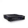
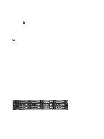
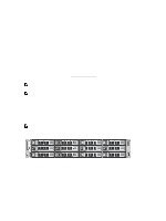
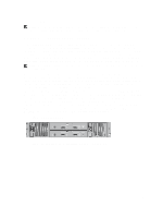
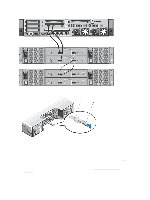
• Tera Term Pro NOTE: The listed terminal emulation applications are not the only ones that will work with the DR Series system. This list is only intended to provide examples of terminal emulation applications that can be used. DR Series - Expansion Shelf Cabling The 2.0 release enables each DR Series system appliance that is capable of supporting additional storage capacity to install and connect up to two Dell PowerVault MD1200 data storage expansion shelf enclosures. Each of the expansion shelf enclosures contains 12 physical disks that provide additional data storage capacity for a basic DR Series system. The supported data storage expansion shelves can be added in 1 Terabyte (TB), 2 TB, or 3 TB hard drive capacities. Figures 1 and 2 are diagrams that display the recommended method for connecting the cabling between the DR4000/ DR4100 PERC controller card to the appropriate connectors on the rear of the Dell MD1200 expansion shelf enclosure. NOTE: The 300 Gigabyte (GB) drive capacity (2.7 TB) version of the DR Series system does not support the addition of expansion shelf enclosures. Make sure that the Dell MD1200 front panel selector switch is set to its Unified mode (with the switch set to its "up" position, indicated by a single Volume icon). Figure 1 shows the SAS In ports on the Enclosure Management Module (EMM) on the rear of the Dell MD1200. Figure 2 shows the recommended redundant path cabling configuration, which includes cable connections from both PERC H800 connectors on the DR4000 system (or the PERC H810 on a DR4100 system) to the two SAS In ports on the EMM rear chassis of the MD1200. If you plan on installing the second of the two supported expansion shelf enclosures in Release 2.0, then the two SAS In ports on the rear chassis of the EMM on the second enclosure are daisy-chained to the two SAS Out ports on the EMM rear chassis on the first enclosure. This is considered a redundant mode connection via the SAS In/Out connectors on the enclosures with the DR Series system appliance (see Figures 1, 2, and 3 for more information). If you install a second enclosure and cable it as described here, make sure to set the enclosure mode switch on the MD1200 front chassis to the top (unified mode) positions. For more information, see Dell PowerVault MD1200 and MD1220 Storage Enclosures Hardware Owner's Manual at support.dell.com/manuals. • Figure 1, MD1200 Rear Chassis • Figure 2, Unified Mode Daisy-Chained Redundant Path MD1200 Enclosures 29
-
 1
1 -
2
-
3
-
4
-
5
-
6
-
7
-
8
-
9
-
10
-
11
-
12
-
13
-
14
-
15
-
16
-
17
-
18
-
19
-
20
-
21
-
22
-
23
-
 24
24 -
 25
25 -
 26
26 -
 27
27 -
 28
28 -
 29
29 -
 30
30 -
 31
31 -
 32
32 -
 33
33 -
 34
34 -
35
-
36
-
37
-
38
-
39
-
40
-
41
-
42
-
43
-
44
-
45
-
46
-
47
-
48
-
49
-
50
-
51
-
52
-
53
-
54
-
55
-
56
-
57
-
58
-
59
-
60
-
61
-
62
-
63
-
64
-
65
-
66
-
67
-
68
-
69
-
70
-
71
-
72
-
73
-
74
-
75
-
76
-
77
-
78
-
79
-
80
-
81
-
82
-
83
-
84
-
85
-
86
-
87
-
88
-
89
-
90
-
91
-
92
-
93
-
94
-
95
-
96
-
97
-
98
-
99
-
100
-
101
-
102
-
103
-
104
-
105
-
106
-
107
-
108
-
109
-
110
-
111
-
112
-
113
-
114
-
115
-
116
-
117
-
118
-
119
-
120
-
121
-
122
-
123
-
124
-
125
-
126
-
127
-
128
-
129
-
130
-
131
-
132
-
133
-
134
-
135
-
136
-
137
-
138
-
139
-
140
-
141
-
142
-
143
-
144
-
145
-
146
-
147
-
148
-
149
-
150
-
151
-
152
-
153
-
154
-
155
-
156
-
157
-
158
-
159
-
160
-
161
-
162
-
163
-
164
-
165
-
166
-
167
-
168
-
169
-
170
-
171
-
172
-
173
-
174
-
175
-
176
 |
 |
