Dell XPS Gen 2 Owner's Manual - Page 107
Frequency Effects LFE channel, Primary IDE drive - power adapter
 |
View all Dell XPS Gen 2 manuals
Add to My Manuals
Save this manual to your list of manuals |
Page 107 highlights
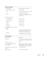
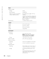
Connectors (continued) Network adapter PS/2 (keyboard and mouse) USB Audio System board connectors: Primary IDE drive Secondary IDE drive Floppy drive Fans (3) I/O Panel Serial ATA (2) Sound Blaster® Audigy™ 2 sound card connectors: Audio IEEE 1394 10/100/1000 Ethernet connector 6-pin mini-DIN two front-panel and six back-panel USB 2.0-compliant connectors one front-panel connector for headphones; one front-panel connector for microphone 40-pin connector 40-pin connector 34-pin connector 3-pin connector 34-pin connector 7-pin connector five connectors for line-in, line-out, microphone, surround, and center/LowFrequency Effects (LFE) channel one front-panel 6-pin serial connector; one back-panel 6-pin serial connector Controls and Lights Power control Power light Hard-drive access light Link integrity light (on integrated network adapter) Activity light (on integrated network adapter) Diagnostic lights push button green light on power button-blinking green in sleep state; solid green for poweron state green green light for 10-Mb operation; orange light for 100-Mb operation; yellow light for 1000-Mbps (or 1-Gbps) operation yellow blinking light four lights on the back panel Appendix 107
-
 1
1 -
2
-
3
-
4
-
5
-
6
-
7
-
8
-
9
-
10
-
11
-
12
-
13
-
14
-
15
-
16
-
17
-
18
-
19
-
20
-
21
-
22
-
23
-
24
-
25
-
26
-
27
-
28
-
29
-
30
-
31
-
32
-
33
-
34
-
35
-
36
-
37
-
38
-
39
-
40
-
41
-
42
-
43
-
44
-
45
-
46
-
47
-
48
-
49
-
50
-
51
-
52
-
53
-
54
-
55
-
56
-
57
-
58
-
59
-
60
-
61
-
62
-
63
-
64
-
65
-
66
-
67
-
68
-
69
-
70
-
71
-
72
-
73
-
74
-
75
-
76
-
77
-
78
-
79
-
80
-
81
-
82
-
83
-
84
-
85
-
86
-
87
-
88
-
89
-
90
-
91
-
92
-
93
-
94
-
95
-
96
-
97
-
98
-
99
-
100
-
101
-
 102
102 -
 103
103 -
 104
104 -
 105
105 -
 106
106 -
 107
107 -
 108
108 -
 109
109 -
 110
110 -
 111
111 -
 112
112 -
113
-
114
-
115
-
116
-
117
-
118
-
119
-
120
-
121
-
122
-
123
-
124
-
125
-
126
-
127
-
128
-
129
-
130
-
131
-
132
-
133
-
134
-
135
-
136
-
137
-
138
-
139
-
140
-
141
-
142
 |
 |
