HP 750c Service Manual - Page 100
Removing the Overdrive Assembly, Remove the clutch and washers
 |
View all HP 750c manuals
Add to My Manuals
Save this manual to your list of manuals |
Page 100 highlights
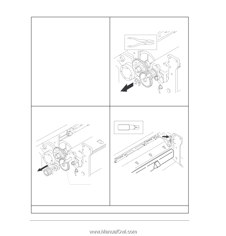
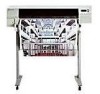
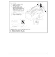
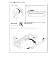
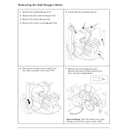
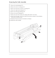
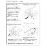
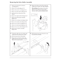
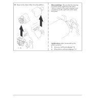
Removing the Overdrive Assembly 1 Remove the window ' page 6Ć13. 2 Remove the center cover ' page 6Ć14. 3 Remove the left endcover ' page 6Ć16. 4 Remove the right endcover ' page 6Ć17. 5 Remove the bail assembly ' page 6Ć45. 6 Remove the encoder strip ' page 6Ć27. 7 Remove the carriage (YĆaxis) motor ' page 6Ć16. 8 Remove the YĆaxis motor holder ' page 6Ć32. 9 Remove the cutter ' page 6Ć33. 10 Remove carriage ' page 6Ć34. 11 Remove the primer ' page 6Ć41. 12 Remove the service station ' page 6Ć42. 13 Remove the clutch retaining ring that secures the overdrive clutch to the overdrive roller. 14 Remove the clutch and washers 15 Remove the overdrive cluster gear from the plotter. 16 Remove the screw from the top of each of the overdrive support mounts. Tx 20 Cluster gear Reassembling: Ensure that you install the clutch as shown in the figure. If you install it in reverse, it will cause inkĆsmearing and paper jam problems. 17 Pull the right side of the overdrive assembly up. 18 Rotate the top of the assembly towards the back of the plotter and pull the assembly to the right, out from the left sideĆplate. Be careful not to lose the bushing on the left side of the overdrive roller. 6-48 Removal and Replacement C4705-90000
-
 1
1 -
2
-
3
-
4
-
5
-
6
-
7
-
8
-
9
-
10
-
11
-
12
-
13
-
14
-
15
-
16
-
17
-
18
-
19
-
20
-
21
-
22
-
23
-
24
-
25
-
26
-
27
-
28
-
29
-
30
-
31
-
32
-
33
-
34
-
35
-
36
-
37
-
38
-
39
-
40
-
41
-
42
-
43
-
44
-
45
-
46
-
47
-
48
-
49
-
50
-
51
-
52
-
53
-
54
-
55
-
56
-
57
-
58
-
59
-
60
-
61
-
62
-
63
-
64
-
65
-
66
-
67
-
68
-
69
-
70
-
71
-
72
-
73
-
74
-
75
-
76
-
77
-
78
-
79
-
80
-
81
-
82
-
83
-
84
-
85
-
86
-
87
-
88
-
89
-
90
-
91
-
92
-
93
-
94
-
 95
95 -
 96
96 -
 97
97 -
 98
98 -
 99
99 -
 100
100 -
 101
101 -
 102
102 -
 103
103 -
 104
104 -
 105
105 -
106
-
107
-
108
-
109
-
110
-
111
-
112
-
113
-
114
-
115
-
116
-
117
-
118
-
119
-
120
-
121
-
122
-
123
-
124
-
125
-
126
-
127
-
128
-
129
-
130
-
131
-
132
-
133
-
134
-
135
-
136
-
137
-
138
-
139
-
140
-
141
-
142
-
143
-
144
-
145
-
146
-
147
-
148
-
149
-
150
-
151
-
152
-
153
-
154
-
155
-
156
-
157
-
158
-
159
-
160
-
161
-
162
-
163
-
164
-
165
-
166
-
167
-
168
-
169
-
170
-
171
-
172
-
173
-
174
-
175
-
176
-
177
-
178
-
179
-
180
-
181
-
182
-
183
-
184
-
185
-
186
-
187
-
188
-
189
-
190
-
191
-
192
-
193
-
194
-
195
-
196
-
197
-
198
-
199
-
200
-
201
-
202
-
203
-
204
-
205
-
206
-
207
-
208
-
209
-
210
-
211
-
212
-
213
-
214
-
215
-
216
-
217
-
218
-
219
-
220
-
221
-
222
-
223
-
224
-
225
-
226
-
227
-
228
-
229
-
230
-
231
-
232
-
233
-
234
-
235
-
236
-
237
-
238
-
239
-
240
-
241
-
242
-
243
-
244
-
245
-
246
-
247
-
248
-
249
-
250
-
251
-
252
-
253
-
254
-
255
-
256
-
257
-
258
-
259
-
260
-
261
-
262
-
263
-
264
-
265
-
266
-
267
-
268
-
269
-
270
-
271
-
272
-
273
-
274
-
275
-
276
-
277
-
278
-
279
-
280
-
281
-
282
-
283
-
284
-
285
-
286
-
287
-
288
 |
 |