HP 750c Service Manual - Page 78
Remove the two screws that secure the, Disconnect the flat encoder cable from
 |
View all HP 750c manuals
Add to My Manuals
Save this manual to your list of manuals |
Page 78 highlights
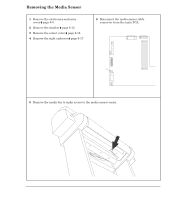
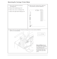
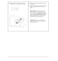
9 Remove the two screws that secure the media motor to the mediaĆmotor mount. Tx 15 10 Pull the media motor towards the rear of the plotter. 11 Disconnect the flat encoder cable from the motor, and lift the motor clear of the plotter. Reinstalling: The worm pinion and driveĆroller gear mesh slightly during use. Do not install a new motor and an old gear, or vice versa: install the gear that comes with the motor. Apply the grease that comes with the new motor onto the worm pinion and driveĆroller gear. Calibration: After reassembling the plotter, perform the accuracy calibration (Details ' page 7Ć6). 6-26 Removal and Replacement C4705-90000
-
 1
1 -
2
-
3
-
4
-
5
-
6
-
7
-
8
-
9
-
10
-
11
-
12
-
13
-
14
-
15
-
16
-
17
-
18
-
19
-
20
-
21
-
22
-
23
-
24
-
25
-
26
-
27
-
28
-
29
-
30
-
31
-
32
-
33
-
34
-
35
-
36
-
37
-
38
-
39
-
40
-
41
-
42
-
43
-
44
-
45
-
46
-
47
-
48
-
49
-
50
-
51
-
52
-
53
-
54
-
55
-
56
-
57
-
58
-
59
-
60
-
61
-
62
-
63
-
64
-
65
-
66
-
67
-
68
-
69
-
70
-
71
-
72
-
 73
73 -
 74
74 -
 75
75 -
 76
76 -
 77
77 -
 78
78 -
 79
79 -
 80
80 -
 81
81 -
 82
82 -
 83
83 -
84
-
85
-
86
-
87
-
88
-
89
-
90
-
91
-
92
-
93
-
94
-
95
-
96
-
97
-
98
-
99
-
100
-
101
-
102
-
103
-
104
-
105
-
106
-
107
-
108
-
109
-
110
-
111
-
112
-
113
-
114
-
115
-
116
-
117
-
118
-
119
-
120
-
121
-
122
-
123
-
124
-
125
-
126
-
127
-
128
-
129
-
130
-
131
-
132
-
133
-
134
-
135
-
136
-
137
-
138
-
139
-
140
-
141
-
142
-
143
-
144
-
145
-
146
-
147
-
148
-
149
-
150
-
151
-
152
-
153
-
154
-
155
-
156
-
157
-
158
-
159
-
160
-
161
-
162
-
163
-
164
-
165
-
166
-
167
-
168
-
169
-
170
-
171
-
172
-
173
-
174
-
175
-
176
-
177
-
178
-
179
-
180
-
181
-
182
-
183
-
184
-
185
-
186
-
187
-
188
-
189
-
190
-
191
-
192
-
193
-
194
-
195
-
196
-
197
-
198
-
199
-
200
-
201
-
202
-
203
-
204
-
205
-
206
-
207
-
208
-
209
-
210
-
211
-
212
-
213
-
214
-
215
-
216
-
217
-
218
-
219
-
220
-
221
-
222
-
223
-
224
-
225
-
226
-
227
-
228
-
229
-
230
-
231
-
232
-
233
-
234
-
235
-
236
-
237
-
238
-
239
-
240
-
241
-
242
-
243
-
244
-
245
-
246
-
247
-
248
-
249
-
250
-
251
-
252
-
253
-
254
-
255
-
256
-
257
-
258
-
259
-
260
-
261
-
262
-
263
-
264
-
265
-
266
-
267
-
268
-
269
-
270
-
271
-
272
-
273
-
274
-
275
-
276
-
277
-
278
-
279
-
280
-
281
-
282
-
283
-
284
-
285
-
286
-
287
-
288
 |
 |
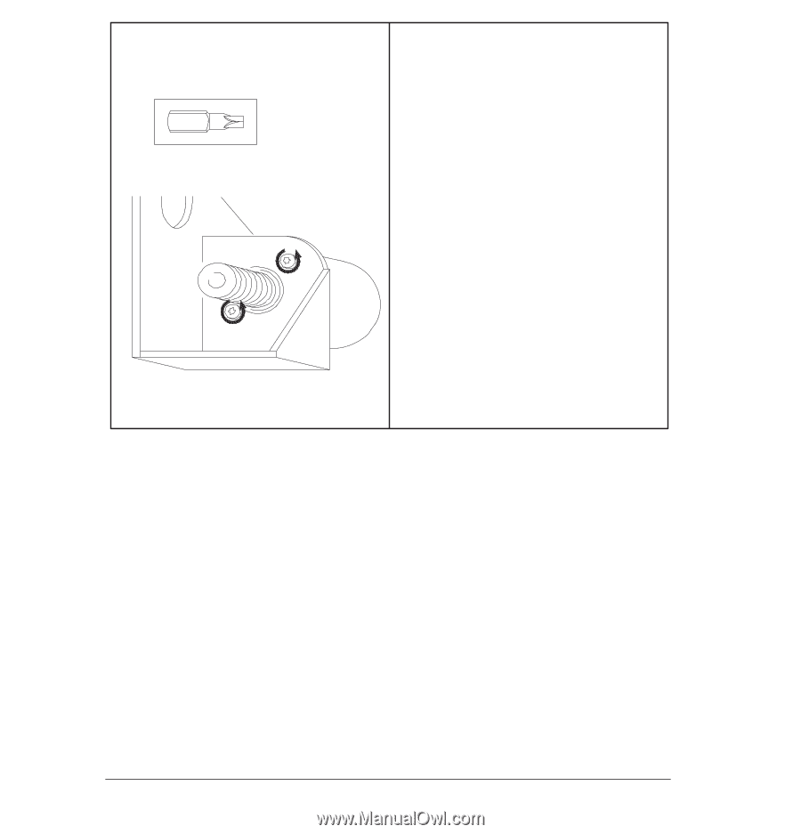
9
Remove the two screws that secure the
media motor to the mediaĆmotor mount.
10
Pull the media motor towards the rear of
the plotter.
11
Disconnect the flat encoder cable from the
motor, and lift the motor clear of the
plotter.
Reinstalling:
The worm pinion and
driveĆroller gear mesh slightly during use.
Do not install a new motor and an old
gear, or vice versa:
install the gear that
comes with the motor
. Apply the grease
that comes with the new motor onto the
worm pinion and driveĆroller gear.
Calibration:
After reassembling the
plotter, perform the accuracy calibration
(Details
'
page 7Ć6).
Tx 15
6-26
Removal and Replacement
C4705-90000