HP 750c Service Manual - Page 101
Removing the Drive Roller Assembly, mediaĆmotor mount to the right sideplate.
 |
View all HP 750c manuals
Add to My Manuals
Save this manual to your list of manuals |
Page 101 highlights
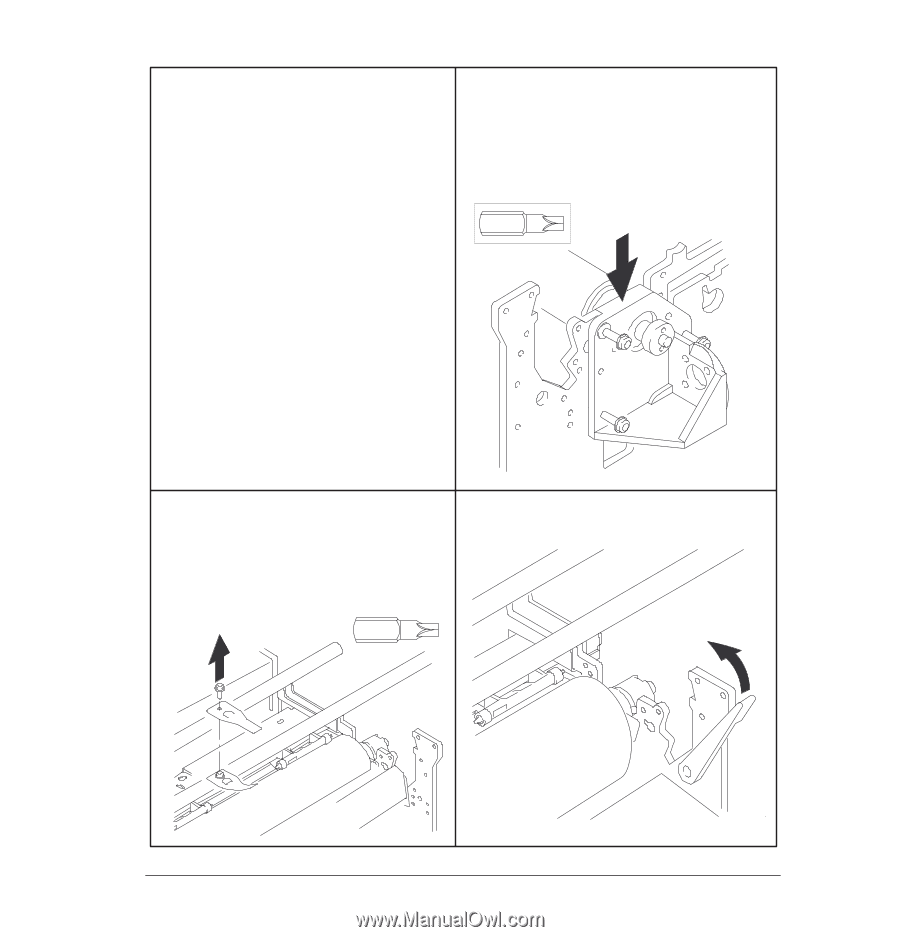
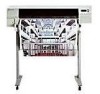
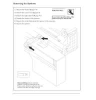
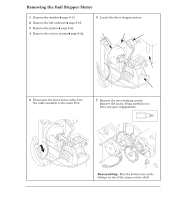
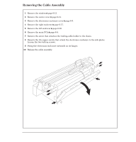
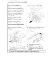
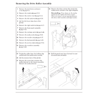
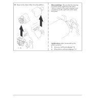
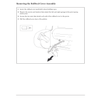
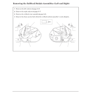
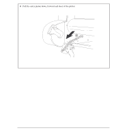
Removing the Drive Roller Assembly 1 Remove the electronicsĆenclosure cover ' page 6Ć5. 2 Remove the window ' page 6Ć13. 3 Remove the center cover ' page 6Ć14. 4 Remove the left endcover ' page 6Ć16. 5 Lift the left front trim clear of the plotter. 6 Remove the right endcover ' page 6Ć17. 7 Remove the frontĆpanel assembly ' page 6Ć18. 8 Remove the carriage motor ' page 6Ć24. 9 Remove the media motor ' page 6Ć25. 10 Remove the encoder strip ' page 6Ć27. 11 Remove the bail assembly ' page 6Ć45. 12 Remove the service station ' page 6Ć42. 13 Remove the overdrive assembly ' page 6Ć48. 14 Remove the three screws that attach the mediaĆmotor mount to the right sideplate. Reinstalling: Press down on the media mount as you replace the three screws. This is to ensure correct spacing between the drive roller and the cartridge nozzles. Tx 20 15 Unclip the cables from the holding clip underneath the mediaĆmotor mount. 16 Lift the mount clear of the plotter. 17 Remove the screw that attaches the media director to the chassis assembly. Remove the media director. Tx 15 18 Pull the pinchĆarm lever forward to raise the pinchĆarm assembly. C4705-90000 Removal and Replacement 6-49
-
 1
1 -
2
-
3
-
4
-
5
-
6
-
7
-
8
-
9
-
10
-
11
-
12
-
13
-
14
-
15
-
16
-
17
-
18
-
19
-
20
-
21
-
22
-
23
-
24
-
25
-
26
-
27
-
28
-
29
-
30
-
31
-
32
-
33
-
34
-
35
-
36
-
37
-
38
-
39
-
40
-
41
-
42
-
43
-
44
-
45
-
46
-
47
-
48
-
49
-
50
-
51
-
52
-
53
-
54
-
55
-
56
-
57
-
58
-
59
-
60
-
61
-
62
-
63
-
64
-
65
-
66
-
67
-
68
-
69
-
70
-
71
-
72
-
73
-
74
-
75
-
76
-
77
-
78
-
79
-
80
-
81
-
82
-
83
-
84
-
85
-
86
-
87
-
88
-
89
-
90
-
91
-
92
-
93
-
94
-
95
-
 96
96 -
 97
97 -
 98
98 -
 99
99 -
 100
100 -
 101
101 -
 102
102 -
 103
103 -
 104
104 -
 105
105 -
 106
106 -
107
-
108
-
109
-
110
-
111
-
112
-
113
-
114
-
115
-
116
-
117
-
118
-
119
-
120
-
121
-
122
-
123
-
124
-
125
-
126
-
127
-
128
-
129
-
130
-
131
-
132
-
133
-
134
-
135
-
136
-
137
-
138
-
139
-
140
-
141
-
142
-
143
-
144
-
145
-
146
-
147
-
148
-
149
-
150
-
151
-
152
-
153
-
154
-
155
-
156
-
157
-
158
-
159
-
160
-
161
-
162
-
163
-
164
-
165
-
166
-
167
-
168
-
169
-
170
-
171
-
172
-
173
-
174
-
175
-
176
-
177
-
178
-
179
-
180
-
181
-
182
-
183
-
184
-
185
-
186
-
187
-
188
-
189
-
190
-
191
-
192
-
193
-
194
-
195
-
196
-
197
-
198
-
199
-
200
-
201
-
202
-
203
-
204
-
205
-
206
-
207
-
208
-
209
-
210
-
211
-
212
-
213
-
214
-
215
-
216
-
217
-
218
-
219
-
220
-
221
-
222
-
223
-
224
-
225
-
226
-
227
-
228
-
229
-
230
-
231
-
232
-
233
-
234
-
235
-
236
-
237
-
238
-
239
-
240
-
241
-
242
-
243
-
244
-
245
-
246
-
247
-
248
-
249
-
250
-
251
-
252
-
253
-
254
-
255
-
256
-
257
-
258
-
259
-
260
-
261
-
262
-
263
-
264
-
265
-
266
-
267
-
268
-
269
-
270
-
271
-
272
-
273
-
274
-
275
-
276
-
277
-
278
-
279
-
280
-
281
-
282
-
283
-
284
-
285
-
286
-
287
-
288
 |
 |