HP 750c Service Manual - Page 92
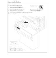
Removing the Starguard Assembly
 |
View all HP 750c manuals
Add to My Manuals
Save this manual to your list of manuals |
Page 92 highlights
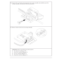
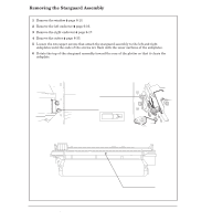
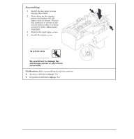
Removing the Starguard Assembly 1 Remove the window ' page 6Ć13. 2 Remove the left endcover ' page 6Ć16. 3 Remove the right endcover ' page 6Ć17. 4 Remove the cutter ' page 6Ć33. 5 Loosen the two upper screws that attach the starguard assembly to the left and right sideplates until the ends of the screws are flush with the inner surfaces of the sideplates. 6 Rotate the top of the starguard assembly toward the rear of the plotter so that it clears the sideplate. Right Starguard Screws (2) Left Starguard Screws (2) Tx 20 6-40 Removal and Replacement Starguard Assembly C4705-90000
-
 1
1 -
2
-
3
-
4
-
5
-
6
-
7
-
8
-
9
-
10
-
11
-
12
-
13
-
14
-
15
-
16
-
17
-
18
-
19
-
20
-
21
-
22
-
23
-
24
-
25
-
26
-
27
-
28
-
29
-
30
-
31
-
32
-
33
-
34
-
35
-
36
-
37
-
38
-
39
-
40
-
41
-
42
-
43
-
44
-
45
-
46
-
47
-
48
-
49
-
50
-
51
-
52
-
53
-
54
-
55
-
56
-
57
-
58
-
59
-
60
-
61
-
62
-
63
-
64
-
65
-
66
-
67
-
68
-
69
-
70
-
71
-
72
-
73
-
74
-
75
-
76
-
77
-
78
-
79
-
80
-
81
-
82
-
83
-
84
-
85
-
86
-
 87
87 -
 88
88 -
 89
89 -
 90
90 -
 91
91 -
 92
92 -
 93
93 -
 94
94 -
 95
95 -
 96
96 -
 97
97 -
98
-
99
-
100
-
101
-
102
-
103
-
104
-
105
-
106
-
107
-
108
-
109
-
110
-
111
-
112
-
113
-
114
-
115
-
116
-
117
-
118
-
119
-
120
-
121
-
122
-
123
-
124
-
125
-
126
-
127
-
128
-
129
-
130
-
131
-
132
-
133
-
134
-
135
-
136
-
137
-
138
-
139
-
140
-
141
-
142
-
143
-
144
-
145
-
146
-
147
-
148
-
149
-
150
-
151
-
152
-
153
-
154
-
155
-
156
-
157
-
158
-
159
-
160
-
161
-
162
-
163
-
164
-
165
-
166
-
167
-
168
-
169
-
170
-
171
-
172
-
173
-
174
-
175
-
176
-
177
-
178
-
179
-
180
-
181
-
182
-
183
-
184
-
185
-
186
-
187
-
188
-
189
-
190
-
191
-
192
-
193
-
194
-
195
-
196
-
197
-
198
-
199
-
200
-
201
-
202
-
203
-
204
-
205
-
206
-
207
-
208
-
209
-
210
-
211
-
212
-
213
-
214
-
215
-
216
-
217
-
218
-
219
-
220
-
221
-
222
-
223
-
224
-
225
-
226
-
227
-
228
-
229
-
230
-
231
-
232
-
233
-
234
-
235
-
236
-
237
-
238
-
239
-
240
-
241
-
242
-
243
-
244
-
245
-
246
-
247
-
248
-
249
-
250
-
251
-
252
-
253
-
254
-
255
-
256
-
257
-
258
-
259
-
260
-
261
-
262
-
263
-
264
-
265
-
266
-
267
-
268
-
269
-
270
-
271
-
272
-
273
-
274
-
275
-
276
-
277
-
278
-
279
-
280
-
281
-
282
-
283
-
284
-
285
-
286
-
287
-
288
 |
 |
1
Remove the window
'
page 6Ć13.
2
Remove the left endcover
'
page 6Ć16.
3
Remove the right endcover
'
page 6Ć17.
4
Remove the cutter
'
page 6Ć33.
5
Loosen the two upper screws that attach the starguard assembly to the left and right
sideplates until the ends of the screws are flush with the inner surfaces of the sideplates.
6
Rotate the top of the starguard assembly toward the rear of the plotter so that it clears the
sideplate.
Right Starguard
Screws (2)
Left Starguard
Screws (2)
Starguard Assembly
Tx 20
6-40
Removal and Replacement
C4705-90000
Removing the Starguard Assembly