HP 750c Service Manual - Page 49
Media Sensor, Drop Sensor, PrimerĆCam Sensor, Main PCA
 |
View all HP 750c manuals
Add to My Manuals
Save this manual to your list of manuals |
Page 49 highlights
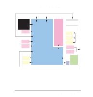
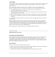
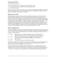
Media Sensor The media sensor is an optical sensor and is mounted towards the right end of the entry platen. Two articulated levers block the optical path between the emitter and the receiver when media is not loaded. When media is loaded, both levers are rotated, thus clearing the optical path and changing the sensor state from open to closed. This doubleĆlever system provides the plotter with leading and trailing edgeĆsensing capability (for mediaĆlength measurement). The media sensor is electrically connected to the main PCA. Drop Sensor The drop sensor is an infrared detector mounted in the service station. It is used to test whether the nozzles in the cartridges are operating properly. It is part of a dropĆdetection system that measures the time from the firing of a nozzle to the sensing of a drop (typically < 900 msec). The operation of the sensor system depends upon an illuminated infrared optical path, in which the received power is modulated a small amount by a drop passing through an aperture on the way to the waste containment system. The illumination is provided by an infrared LED, which is regulated by an automatic power control to provide a fixed operating point in the optical receiver photoĆdiode. The automatic power control compensates for contamination, device aging and environmental effects. PrimerĆCam Sensor An optical sensor mounted on the primer assembly determines the initial position of the primer assembly cam. When the stepper motor that drives the primer assembly rotates in one direction, it obtains the values for selecting each cartridge for priming. When rotated in the opposite direction, a clutch engages a diaphragm to provide the vacuum for priming. Printed Circuit Assembly (PCA) Overview Main PCA There are two clocks on the main PCA. The main clock provides a 32.00ĆMHz signal directly to the main processor. The 32.00 MHz are divided by the main processor, and the resulting signal is provided to the processorĆsupport ASIC and the BiĆtronics gate array. A separate clock provides a 12ĆMHz signal to the servo processor. To perform its functions, the main processor must have access to its memories (ROM and DRAM). To create plots at the direction of an external controller, it must be able to communicate with the controller by its interfaces (MIO, BiĆtronics and RSĆ232ĆC). To address the ROM or DRAM interface, the main processor places the appropriate address on the address bus and reads or writes the data directly. Data is passed to the main processor by a transceiver in the case of ROM or DRAM SIMM data. MIO or BiĆtronics input and output data passes through another transceiver on its way to the main processor. C4705-90000 Functional Overview 5-7
-
 1
1 -
2
-
3
-
4
-
5
-
6
-
7
-
8
-
9
-
10
-
11
-
12
-
13
-
14
-
15
-
16
-
17
-
18
-
19
-
20
-
21
-
22
-
23
-
24
-
25
-
26
-
27
-
28
-
29
-
30
-
31
-
32
-
33
-
34
-
35
-
36
-
37
-
38
-
39
-
40
-
41
-
42
-
43
-
 44
44 -
 45
45 -
 46
46 -
 47
47 -
 48
48 -
 49
49 -
 50
50 -
 51
51 -
 52
52 -
 53
53 -
 54
54 -
55
-
56
-
57
-
58
-
59
-
60
-
61
-
62
-
63
-
64
-
65
-
66
-
67
-
68
-
69
-
70
-
71
-
72
-
73
-
74
-
75
-
76
-
77
-
78
-
79
-
80
-
81
-
82
-
83
-
84
-
85
-
86
-
87
-
88
-
89
-
90
-
91
-
92
-
93
-
94
-
95
-
96
-
97
-
98
-
99
-
100
-
101
-
102
-
103
-
104
-
105
-
106
-
107
-
108
-
109
-
110
-
111
-
112
-
113
-
114
-
115
-
116
-
117
-
118
-
119
-
120
-
121
-
122
-
123
-
124
-
125
-
126
-
127
-
128
-
129
-
130
-
131
-
132
-
133
-
134
-
135
-
136
-
137
-
138
-
139
-
140
-
141
-
142
-
143
-
144
-
145
-
146
-
147
-
148
-
149
-
150
-
151
-
152
-
153
-
154
-
155
-
156
-
157
-
158
-
159
-
160
-
161
-
162
-
163
-
164
-
165
-
166
-
167
-
168
-
169
-
170
-
171
-
172
-
173
-
174
-
175
-
176
-
177
-
178
-
179
-
180
-
181
-
182
-
183
-
184
-
185
-
186
-
187
-
188
-
189
-
190
-
191
-
192
-
193
-
194
-
195
-
196
-
197
-
198
-
199
-
200
-
201
-
202
-
203
-
204
-
205
-
206
-
207
-
208
-
209
-
210
-
211
-
212
-
213
-
214
-
215
-
216
-
217
-
218
-
219
-
220
-
221
-
222
-
223
-
224
-
225
-
226
-
227
-
228
-
229
-
230
-
231
-
232
-
233
-
234
-
235
-
236
-
237
-
238
-
239
-
240
-
241
-
242
-
243
-
244
-
245
-
246
-
247
-
248
-
249
-
250
-
251
-
252
-
253
-
254
-
255
-
256
-
257
-
258
-
259
-
260
-
261
-
262
-
263
-
264
-
265
-
266
-
267
-
268
-
269
-
270
-
271
-
272
-
273
-
274
-
275
-
276
-
277
-
278
-
279
-
280
-
281
-
282
-
283
-
284
-
285
-
286
-
287
-
288
 |
 |
