HP 750c Service Manual - Page 174
Service Configuration Plot, The RSĆ232ĆC/MIO configurations.
 |
View all HP 750c manuals
Add to My Manuals
Save this manual to your list of manuals |
Page 174 highlights
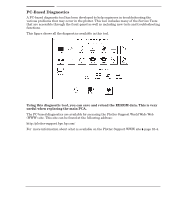
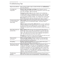
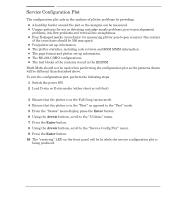
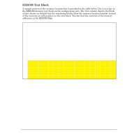
Service Configuration Plot The configuration plot aids in the analysis of plotter problems by providing: D A hardclip border around the plot so the margins can be measured. D Unique patterns for use in detecting cartridge nozzle problems, penĆtoĆpen alignment problems, inkĆflow problems and verticalĆline straightness. D Four XĆshaped marks (crossĆhairs) for measuring plotter penĆtoĆpen accuracy (the centers of the crossĆhairs should be 500 mm apart). D Pen/palette set up information. D The plotter statistics, including code revision and ROM SIMM information. D The page format and plotter setĆup information. D The RSĆ232ĆC/MIO configurations. D The text blocks of the contents stored in the EEROM. Draft Mode should not be used when performing the configuration plot as the patterns drawn will be different than described above. To run the configuration plot, perform the following steps: 1 Switch the power ON. 2 Load DĆsize or EĆsize media (either sheet or rollĆfeed). Make sure D-size or E-size media is selected in the front-panel. 3 Ensure that the plotter is in the Full (long) menu mode. 4 Ensure that the plotter is in the Best" as opposed to the Fast" mode. 5 From the Status" menu display, press the Enter button. 6 Using the Arrow buttons, scroll to the Utilities" menu. 7 Press the Enter button. 8 Using the Arrow buttons, scroll to the Service Config Plot" menu. 9 Press the Enter button. 10 The receiving" LED on the front panel will be lit while the service configuration plot is being produced. 8-56 Troubleshooting C4705-90000
-
 1
1 -
2
-
3
-
4
-
5
-
6
-
7
-
8
-
9
-
10
-
11
-
12
-
13
-
14
-
15
-
16
-
17
-
18
-
19
-
20
-
21
-
22
-
23
-
24
-
25
-
26
-
27
-
28
-
29
-
30
-
31
-
32
-
33
-
34
-
35
-
36
-
37
-
38
-
39
-
40
-
41
-
42
-
43
-
44
-
45
-
46
-
47
-
48
-
49
-
50
-
51
-
52
-
53
-
54
-
55
-
56
-
57
-
58
-
59
-
60
-
61
-
62
-
63
-
64
-
65
-
66
-
67
-
68
-
69
-
70
-
71
-
72
-
73
-
74
-
75
-
76
-
77
-
78
-
79
-
80
-
81
-
82
-
83
-
84
-
85
-
86
-
87
-
88
-
89
-
90
-
91
-
92
-
93
-
94
-
95
-
96
-
97
-
98
-
99
-
100
-
101
-
102
-
103
-
104
-
105
-
106
-
107
-
108
-
109
-
110
-
111
-
112
-
113
-
114
-
115
-
116
-
117
-
118
-
119
-
120
-
121
-
122
-
123
-
124
-
125
-
126
-
127
-
128
-
129
-
130
-
131
-
132
-
133
-
134
-
135
-
136
-
137
-
138
-
139
-
140
-
141
-
142
-
143
-
144
-
145
-
146
-
147
-
148
-
149
-
150
-
151
-
152
-
153
-
154
-
155
-
156
-
157
-
158
-
159
-
160
-
161
-
162
-
163
-
164
-
165
-
166
-
167
-
168
-
 169
169 -
 170
170 -
 171
171 -
 172
172 -
 173
173 -
 174
174 -
 175
175 -
 176
176 -
 177
177 -
 178
178 -
 179
179 -
180
-
181
-
182
-
183
-
184
-
185
-
186
-
187
-
188
-
189
-
190
-
191
-
192
-
193
-
194
-
195
-
196
-
197
-
198
-
199
-
200
-
201
-
202
-
203
-
204
-
205
-
206
-
207
-
208
-
209
-
210
-
211
-
212
-
213
-
214
-
215
-
216
-
217
-
218
-
219
-
220
-
221
-
222
-
223
-
224
-
225
-
226
-
227
-
228
-
229
-
230
-
231
-
232
-
233
-
234
-
235
-
236
-
237
-
238
-
239
-
240
-
241
-
242
-
243
-
244
-
245
-
246
-
247
-
248
-
249
-
250
-
251
-
252
-
253
-
254
-
255
-
256
-
257
-
258
-
259
-
260
-
261
-
262
-
263
-
264
-
265
-
266
-
267
-
268
-
269
-
270
-
271
-
272
-
273
-
274
-
275
-
276
-
277
-
278
-
279
-
280
-
281
-
282
-
283
-
284
-
285
-
286
-
287
-
288
 |
 |