HP Carrier-grade cc3300 User Information and Service Guide - HP Carrier-Grade - Page 101
Replacing a Processor
 |
View all HP Carrier-grade cc3300 manuals
Add to My Manuals
Save this manual to your list of manuals |
Page 101 highlights
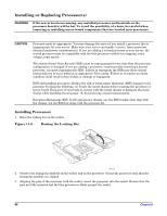
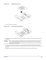
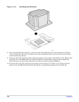
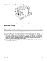
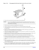
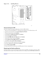
Figure 11-12. Installing the Heatsink Clip B A C TP111 11. Install the second heatsink clip as described in the preceding steps. Replacing a Processor 1. Observe the safety and ESD precautions at the beginning of this chapter and the additional cautions given here. NOTE Removing the fan assembly makes processor removal and installation easier to accomplish. 2. Disconnect 4 fan power connectors from the FPIO board sockets. 3. Loosen the captive screw that secures the fan assembly, and lift the fan assembly from the board. 4. Using a slot screwdriver, disengage the retention clip from the heatsink and processor socket. (One end of the clip has an extended tab to facilitate clip removal.) Press the center of the clip down while using the screwdriver to pull the retention clip from the tab on the RM bracket. Insert the screwdriver blade into the small slot on the end of the retention clip, and pull the clip free of the tab. (See Figure 11-13.) The end of the retention clip will pop off the RM bracket. 5. Remove the clip. If necessary, free the clip from the other end of RM bracket by repeating the process described in the preceding step. Chapter 9 101
-
 1
1 -
2
-
3
-
4
-
5
-
6
-
7
-
8
-
9
-
10
-
11
-
12
-
13
-
14
-
15
-
16
-
17
-
18
-
19
-
20
-
21
-
22
-
23
-
24
-
25
-
26
-
27
-
28
-
29
-
30
-
31
-
32
-
33
-
34
-
35
-
36
-
37
-
38
-
39
-
40
-
41
-
42
-
43
-
44
-
45
-
46
-
47
-
48
-
49
-
50
-
51
-
52
-
53
-
54
-
55
-
56
-
57
-
58
-
59
-
60
-
61
-
62
-
63
-
64
-
65
-
66
-
67
-
68
-
69
-
70
-
71
-
72
-
73
-
74
-
75
-
76
-
77
-
78
-
79
-
80
-
81
-
82
-
83
-
84
-
85
-
86
-
87
-
88
-
89
-
90
-
91
-
92
-
93
-
94
-
95
-
 96
96 -
 97
97 -
 98
98 -
 99
99 -
 100
100 -
 101
101 -
 102
102 -
 103
103 -
 104
104 -
 105
105 -
 106
106 -
107
-
108
-
109
-
110
-
111
-
112
-
113
-
114
-
115
-
116
-
117
-
118
-
119
-
120
-
121
-
122
-
123
-
124
-
125
 |
 |
