HP Carrier-grade cc3300 User Information and Service Guide - HP Carrier-Grade - Page 21
Internal Chassis Features
 |
View all HP Carrier-grade cc3300 manuals
Add to My Manuals
Save this manual to your list of manuals |
Page 21 highlights
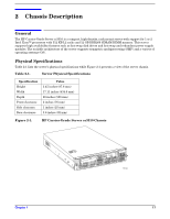
Back Panel Figure 2-4 shows the back panel view of the server and Table 2-4 lists the features of the back panel. The back panel of the AC-powered server is similar (except for the power supplies). Figure 2-4. Back Panel (DC Version) A B C D E F O N M L KJ I H G TP250 Table 2-4. Back Panel Features Item Description A PCI card bracket (low profile) B RJ-45 NIC2 connector - green status LED / yellow status LED C DB15 alarm connector D PCI card bracket (full-height) E DC power input (primary) F DC power input (redundant) G Power supply module, redundant (system accessory) H Power supply module, primary I USB connector 2 J RJ-45 serial 2 port K PS/2 mouse/keyboard connector - requires dongle (Y cable) to connect both keyboard and mouse L RJ-45 NIC1 connector M U-320 SCSI connector N Video connector O USB connector 1 Internal Chassis Features Figure 2-5 shows the location of the connectors and components on the server board. Chapter 8 89
-
 1
1 -
2
-
3
-
4
-
5
-
6
-
7
-
8
-
9
-
10
-
11
-
12
-
13
-
14
-
15
-
 16
16 -
 17
17 -
 18
18 -
 19
19 -
 20
20 -
 21
21 -
 22
22 -
 23
23 -
 24
24 -
 25
25 -
 26
26 -
27
-
28
-
29
-
30
-
31
-
32
-
33
-
34
-
35
-
36
-
37
-
38
-
39
-
40
-
41
-
42
-
43
-
44
-
45
-
46
-
47
-
48
-
49
-
50
-
51
-
52
-
53
-
54
-
55
-
56
-
57
-
58
-
59
-
60
-
61
-
62
-
63
-
64
-
65
-
66
-
67
-
68
-
69
-
70
-
71
-
72
-
73
-
74
-
75
-
76
-
77
-
78
-
79
-
80
-
81
-
82
-
83
-
84
-
85
-
86
-
87
-
88
-
89
-
90
-
91
-
92
-
93
-
94
-
95
-
96
-
97
-
98
-
99
-
100
-
101
-
102
-
103
-
104
-
105
-
106
-
107
-
108
-
109
-
110
-
111
-
112
-
113
-
114
-
115
-
116
-
117
-
118
-
119
-
120
-
121
-
122
-
123
-
124
-
125
 |
 |
