HP Carrier-grade cc3300 User Information and Service Guide - HP Carrier-Grade - Page 98
Installing or Replacing Processors
 |
View all HP Carrier-grade cc3300 manuals
Add to My Manuals
Save this manual to your list of manuals |
Page 98 highlights
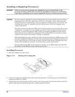
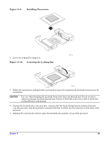
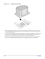
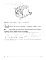
Installing or Replacing Processor(s) WARNING If the server has been running, any installed processor and heatsink on the processor board(s) will be hot. To avoid the possibility of a burn, be careful when removing or installing server board components that are located near processors. CAUTION Processor must be appropriate: You may damage the server if you install a processor that is inappropriate for your server. Make sure your server can handle a newer, faster processor (thermal and power considerations). If you are adding a second processor to your server, the second processor must be compatible with the first processor (within one stepping, same voltage, same speed). The system Sensor Data Records (SDR) must be reprogrammed every time that the processor configuration is changed. If you are adding a processor, or permanently removing a second processor, you must reprogram the SDR. Failure to reprogram the SDR may allow critical system failures to occur without an appropriate Telco alarm. Failure to recognize an alarm condition could result in loss of data or damage to equipment ESD and handling processors: Reduce the risk of electrostatic discharge (ESD) damage to the processor by doing the following: (1) Touch the metal chassis before touching the processor or server board. Keep part of your body in contact with the metal chassis to dissipate the static charge while handling the processor. (2) Avoid moving around unnecessarily. Retention Mechanism (RM): In 2U and greater chassis, use the RM brackets that ship with the chassis, not the RM that ships with the processor kit. Installing Processors 1. Raise the locking bar on the socket. Figure 11-8. Raising the Locking Bar OM14132 2. Observe the triangular symbols on the socket and on the processor. Orient the processor such that the triangular symbols are aligned. 3. Aligning the pins of the processor with the socket, insert the processor into the socket. Ensure that the pins are fully inserted and that the processor is flush against the socket. 98 Chapter 8
-
 1
1 -
2
-
3
-
4
-
5
-
6
-
7
-
8
-
9
-
10
-
11
-
12
-
13
-
14
-
15
-
16
-
17
-
18
-
19
-
20
-
21
-
22
-
23
-
24
-
25
-
26
-
27
-
28
-
29
-
30
-
31
-
32
-
33
-
34
-
35
-
36
-
37
-
38
-
39
-
40
-
41
-
42
-
43
-
44
-
45
-
46
-
47
-
48
-
49
-
50
-
51
-
52
-
53
-
54
-
55
-
56
-
57
-
58
-
59
-
60
-
61
-
62
-
63
-
64
-
65
-
66
-
67
-
68
-
69
-
70
-
71
-
72
-
73
-
74
-
75
-
76
-
77
-
78
-
79
-
80
-
81
-
82
-
83
-
84
-
85
-
86
-
87
-
88
-
89
-
90
-
91
-
92
-
 93
93 -
 94
94 -
 95
95 -
 96
96 -
 97
97 -
 98
98 -
 99
99 -
 100
100 -
 101
101 -
 102
102 -
 103
103 -
104
-
105
-
106
-
107
-
108
-
109
-
110
-
111
-
112
-
113
-
114
-
115
-
116
-
117
-
118
-
119
-
120
-
121
-
122
-
123
-
124
-
125
 |
 |
