HP Carrier-grade cc3300 User Information and Service Guide - HP Carrier-Grade - Page 109
Front Panel Board Connectors FPIO Board
 |
View all HP Carrier-grade cc3300 manuals
Add to My Manuals
Save this manual to your list of manuals |
Page 109 highlights
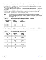
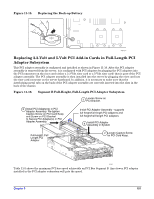
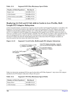
2 Slots (bottom and middle) 3 Slots 66 MHz PCI-X 66 MHz PCI-X Front Panel Board Connectors (FPIO Board) Table 11-7 shows all the connectors on the FPIO server board, the interconnect used for each connector, and the destination for the interconnect. In addition, the first column references the connector location (see Figure 11-18). Table 11-7. FPIO Board Connections Loc A B C D E F G H I J K L M N O P Q Ref Des J5A1 J2A1 J7A1 J5B1 J6A1 J1A1 J9A1 J8A3 J8A2 J8A1 J9D1 J5D1 J3A1 J1C1 J4A1 J9D2 J9A2 Function Interconnect 2x20 IDE connector IDE cable 68-Pin blind mate receptacle CDFDD I/F 2x10 system fan cntrl conn Fan cntrl cbl 68 pin SCSI connector SCSI BB Cbl 2x8 Alarms connector Alarms cable 2x3 P/S power connector P/S harness 1x3 Server fan 1 conn Fan 1 harness 1x3 Server fan 2 conn Fan 2 harness 1x3 Server fan 3 conn Fan 3 harness 1x3 Server fan 4 conn Fan 4 harness 80-Pin SCA connector SCSI Flex 1 80-Pin SCA connector SCSI Flex 2 2x5 USB connector USB cable 2x17 floppy conn Floppy cable 2x17 front panel conn 2mm FP cable RJ45 COM2/dual USB conn N/C I2C connector IPMB harness Connects to Baseboard IDE connector CDROM carrier Baseboard fan connectors Baseboard SCSI connector Server chassis back Power supply assembly Fan 1 Fan 2 Fan 3 Fan 4 SCSI disk drive 1 SCSI disk drive 2 Baseboard USB connector Baseboard Floppy connector Baseboard front panel connector Baseboard IPMB conn Chapter 9 109
-
 1
1 -
2
-
3
-
4
-
5
-
6
-
7
-
8
-
9
-
10
-
11
-
12
-
13
-
14
-
15
-
16
-
17
-
18
-
19
-
20
-
21
-
22
-
23
-
24
-
25
-
26
-
27
-
28
-
29
-
30
-
31
-
32
-
33
-
34
-
35
-
36
-
37
-
38
-
39
-
40
-
41
-
42
-
43
-
44
-
45
-
46
-
47
-
48
-
49
-
50
-
51
-
52
-
53
-
54
-
55
-
56
-
57
-
58
-
59
-
60
-
61
-
62
-
63
-
64
-
65
-
66
-
67
-
68
-
69
-
70
-
71
-
72
-
73
-
74
-
75
-
76
-
77
-
78
-
79
-
80
-
81
-
82
-
83
-
84
-
85
-
86
-
87
-
88
-
89
-
90
-
91
-
92
-
93
-
94
-
95
-
96
-
97
-
98
-
99
-
100
-
101
-
102
-
103
-
 104
104 -
 105
105 -
 106
106 -
 107
107 -
 108
108 -
 109
109 -
 110
110 -
 111
111 -
 112
112 -
 113
113 -
 114
114 -
115
-
116
-
117
-
118
-
119
-
120
-
121
-
122
-
123
-
124
-
125
 |
 |
