HP Carrier-grade cc3300 User Information and Service Guide - HP Carrier-Grade - Page 31
Power Supplies, DC Power Subsystem
 |
View all HP Carrier-grade cc3300 manuals
Add to My Manuals
Save this manual to your list of manuals |
Page 31 highlights
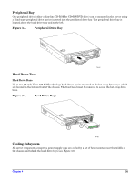
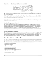
Power Supplies The power supply cage shown in Figure 3-3 is accessed from the rear of the chassis. The power supply cage supports up to two hot-swap power supplies (either AC input or DC input) in a (1+1) redundant configuration. A power supply filler module (shown in Figure 3-3) for the empty power supply site is supplied for servers without redundancy. Only the DC input version is NEBS certified. Figure 3-3. Non-redundant AC-Power Supply Subsystem (Filler Module Shown) DC Power Subsystem This section defines the features of the DC input switching power subsystem. Features • 450-Watt output capability in full DC input voltage range • Power Good indication LEDs • Internal cooling fans with multi-speed capability • Remote sense of 3.3-Volt, 5-Volt, and 12-Volt DC outputs • DC_OK circuitry for brown-out protection and recovery • Built-in load sharing capability • Built-in overloading protection capability • Onboard Field Replaceable Unit (FRU) information • I2C interface for server management functions • Integral handle for insertion/extraction Introduction The DC version of the server uses a -48 to -60 VDC input switching power subsystem, which provides up to 450 Watts with -48 to -60 VDC input and with current and remote sense regulation. The power subsystem consists of one or two 450-Watt power supply modules. A server with two modules forms a redundant, hotswappable (1+1) power subsystem. Chapter 4 31
-
 1
1 -
2
-
3
-
4
-
5
-
6
-
7
-
8
-
9
-
10
-
11
-
12
-
13
-
14
-
15
-
16
-
17
-
18
-
19
-
20
-
21
-
22
-
23
-
24
-
25
-
 26
26 -
 27
27 -
 28
28 -
 29
29 -
 30
30 -
 31
31 -
 32
32 -
 33
33 -
 34
34 -
 35
35 -
 36
36 -
37
-
38
-
39
-
40
-
41
-
42
-
43
-
44
-
45
-
46
-
47
-
48
-
49
-
50
-
51
-
52
-
53
-
54
-
55
-
56
-
57
-
58
-
59
-
60
-
61
-
62
-
63
-
64
-
65
-
66
-
67
-
68
-
69
-
70
-
71
-
72
-
73
-
74
-
75
-
76
-
77
-
78
-
79
-
80
-
81
-
82
-
83
-
84
-
85
-
86
-
87
-
88
-
89
-
90
-
91
-
92
-
93
-
94
-
95
-
96
-
97
-
98
-
99
-
100
-
101
-
102
-
103
-
104
-
105
-
106
-
107
-
108
-
109
-
110
-
111
-
112
-
113
-
114
-
115
-
116
-
117
-
118
-
119
-
120
-
121
-
122
-
123
-
124
-
125
 |
 |
