HP Carrier-grade cc3300 User Information and Service Guide - HP Carrier-Grade - Page 36
Ambient Temperature Control, Server Management Summary, Server Board Management Controller
 |
View all HP Carrier-grade cc3300 manuals
Add to My Manuals
Save this manual to your list of manuals |
Page 36 highlights
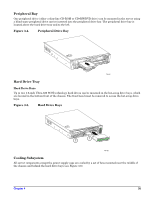
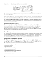
Figure 3-6. Fan Array with Four Fans Installed TP107 The server comes in a non-redundant, four-fan configuration that consists of two 80-mm x 38-mm fans and two 40-mm x 28-mm fans. Air flows in through the front bezel over the peripheral bay and the hard drive bays, passes through the fans and over the baseboard, and exhausts through the rear of the chassis. Each fan provides tachometer signal output to the server baseboard to indicate a fan failure. The cooling subsystem contains a fan array (see Figure 3-6) consisting of two 80-mm x 38-mm fans and two 40-mm x 28-mm fans to cool the server board and other components. A fan failure is indicated by one of the fault LEDs located on the front panel. Ambient Temperature Control The server baseboard contains a Pulse-Width-Modulation (PWM) circuit, which cycles the 12-VDC fan voltage to provide quiet operation when ambient temperature is low and no fan failures exist. There are 16 fan speed settings between 20°C and 35°C, with the lowest fan speed setting at 20°C or below. When the room ambient temperature exceeds 35°C, the fan control circuit ceases cycling and delivers 12 VDC. Following a room temperature excursion above 35°C the fan voltage does not reenter PWM mode until the room temperature drops below 35°C and all fans are operational. Server Management Summary The baseboard server management architecture features a Baseboard Management Controller (BMC), which autonomously monitors server status and provides the interface to server management control functions. This controller is responsible for controlling system power, resets, monitoring voltages, temperatures, fans, and communicating with secondary controllers on its Intelligent Platform Management Bus (IPMB). Server Board Management Controller The BMC on the system baseboard provides server management monitoring capabilities. A flash memory is associated with the BMC that holds the operational code, Sensor Data Records (SDRs), and System Event Log (SEL). There is also a serial EEPROM that holds the BMC configuration defaults and FRU information. The various server management functions provided by the BMC are listed as follows: • Baseboard voltage monitoring • Fan failure detection • Fan speed control • Processor voltage monitoring • Processor presence detection • Processor Internal Error (IERR) monitoring • Fault Resilient Booting (FRB) • Processor disable control 36 Chapter 3
-
 1
1 -
2
-
3
-
4
-
5
-
6
-
7
-
8
-
9
-
10
-
11
-
12
-
13
-
14
-
15
-
16
-
17
-
18
-
19
-
20
-
21
-
22
-
23
-
24
-
25
-
26
-
27
-
28
-
29
-
30
-
 31
31 -
 32
32 -
 33
33 -
 34
34 -
 35
35 -
 36
36 -
 37
37 -
 38
38 -
 39
39 -
 40
40 -
 41
41 -
42
-
43
-
44
-
45
-
46
-
47
-
48
-
49
-
50
-
51
-
52
-
53
-
54
-
55
-
56
-
57
-
58
-
59
-
60
-
61
-
62
-
63
-
64
-
65
-
66
-
67
-
68
-
69
-
70
-
71
-
72
-
73
-
74
-
75
-
76
-
77
-
78
-
79
-
80
-
81
-
82
-
83
-
84
-
85
-
86
-
87
-
88
-
89
-
90
-
91
-
92
-
93
-
94
-
95
-
96
-
97
-
98
-
99
-
100
-
101
-
102
-
103
-
104
-
105
-
106
-
107
-
108
-
109
-
110
-
111
-
112
-
113
-
114
-
115
-
116
-
117
-
118
-
119
-
120
-
121
-
122
-
123
-
124
-
125
 |
 |
