HP LaserJet M1120 Service Manual - Page 50
Basic operation, Sequence of operation for the base unit
 |
View all HP LaserJet M1120 manuals
Add to My Manuals
Save this manual to your list of manuals |
Page 50 highlights
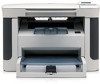
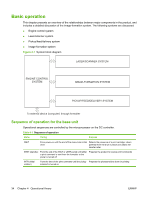
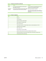
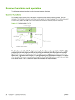
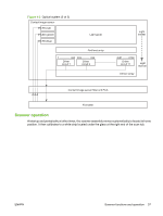
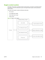
Basic operation This chapter presents an overview of the relationships between major components in the product, and includes a detailed discussion of the image-formation system. The following systems are discussed: ● Engine control system ● Laser/scanner system ● Pickup/feed/delivery system ● Image-formation system Figure 4-1 System block diagram Sequence of operation for the base unit Operational sequences are controlled by the microprocessor on the DC controller. Table 4-1 Sequence of operation Name Timing Purpose WAIT From power-on until the end of the main-motor initial Detects the presence of a print cartridge; clears drive potential from the drum surface and cleans the transfer roller STBY (standby) From the end of the WAIT or LSTR period until either Prepares the product to receive print commands a print command is sent from the formatter or the power is turned off INTR (initial rotation) From the time of the print command until the pickup Prepares the photosensitive drum for printing solenoid is turned on 34 Chapter 4 Operational theory ENWW
-
 1
1 -
2
-
3
-
4
-
5
-
6
-
7
-
8
-
9
-
10
-
11
-
12
-
13
-
14
-
15
-
16
-
17
-
18
-
19
-
20
-
21
-
22
-
23
-
24
-
25
-
26
-
27
-
28
-
29
-
30
-
31
-
32
-
33
-
34
-
35
-
36
-
37
-
38
-
39
-
40
-
41
-
42
-
43
-
44
-
 45
45 -
 46
46 -
 47
47 -
 48
48 -
 49
49 -
 50
50 -
 51
51 -
 52
52 -
 53
53 -
 54
54 -
 55
55 -
56
-
57
-
58
-
59
-
60
-
61
-
62
-
63
-
64
-
65
-
66
-
67
-
68
-
69
-
70
-
71
-
72
-
73
-
74
-
75
-
76
-
77
-
78
-
79
-
80
-
81
-
82
-
83
-
84
-
85
-
86
-
87
-
88
-
89
-
90
-
91
-
92
-
93
-
94
-
95
-
96
-
97
-
98
-
99
-
100
-
101
-
102
-
103
-
104
-
105
-
106
-
107
-
108
-
109
-
110
-
111
-
112
-
113
-
114
-
115
-
116
-
117
-
118
-
119
-
120
-
121
-
122
-
123
-
124
-
125
-
126
-
127
-
128
-
129
-
130
-
131
-
132
-
133
-
134
-
135
-
136
-
137
-
138
-
139
-
140
-
141
-
142
-
143
-
144
-
145
-
146
-
147
-
148
-
149
-
150
-
151
-
152
-
153
-
154
-
155
-
156
-
157
-
158
-
159
-
160
-
161
-
162
-
163
-
164
-
165
-
166
-
167
-
168
-
169
-
170
-
171
-
172
-
173
-
174
-
175
-
176
-
177
-
178
-
179
-
180
-
181
-
182
-
183
-
184
-
185
-
186
-
187
-
188
-
189
-
190
-
191
-
192
-
193
-
194
-
195
-
196
-
197
-
198
-
199
-
200
-
201
-
202
-
203
-
204
-
205
-
206
-
207
-
208
-
209
-
210
-
211
-
212
-
213
-
214
-
215
-
216
-
217
-
218
-
219
-
220
-
221
-
222
-
223
-
224
 |
 |