HP LaserJet M1120 Service Manual - Page 80
WARNING, CAUTION, remove the scanner assembly.
 |
View all HP LaserJet M1120 manuals
Add to My Manuals
Save this manual to your list of manuals |
Page 80 highlights
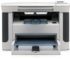
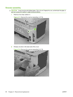
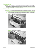
9. Use a small flat-blade screwdriver to release the tabs on each link assembly. WARNING! When the links are disengaged, the scanner assembly can easily fall off of the product base if it is rotated too far toward the back of the product. CAUTION: Do not push too hard on the link tabs or the tabs might break. Figure 5-21 Remove the scanner assembly (9 of 10) 10. Rotate the scanner assembly toward the rear of the product until the rear hinges clear the chassis hinge pins. Lift the scanner assembly off of the product base. CAUTION: Make sure that the scanner lid is supported so that it does not swing open when you remove the scanner assembly. NOTE: Do not lose the two scanner cushions in the scanner support-frame corners when moving the product base. See Scanner cushions on page 70. Figure 5-22 Remove the scanner assembly (10 of 10) 64 Chapter 5 Removal and replacement ENWW
-
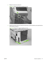
 1
1 -
2
-
3
-
4
-
5
-
6
-
7
-
8
-
9
-
10
-
11
-
12
-
13
-
14
-
15
-
16
-
17
-
18
-
19
-
20
-
21
-
22
-
23
-
24
-
25
-
26
-
27
-
28
-
29
-
30
-
31
-
32
-
33
-
34
-
35
-
36
-
37
-
38
-
39
-
40
-
41
-
42
-
43
-
44
-
45
-
46
-
47
-
48
-
49
-
50
-
51
-
52
-
53
-
54
-
55
-
56
-
57
-
58
-
59
-
60
-
61
-
62
-
63
-
64
-
65
-
66
-
67
-
68
-
69
-
70
-
71
-
72
-
73
-
74
-
 75
75 -
 76
76 -
 77
77 -
 78
78 -
 79
79 -
 80
80 -
 81
81 -
 82
82 -
 83
83 -
 84
84 -
 85
85 -
86
-
87
-
88
-
89
-
90
-
91
-
92
-
93
-
94
-
95
-
96
-
97
-
98
-
99
-
100
-
101
-
102
-
103
-
104
-
105
-
106
-
107
-
108
-
109
-
110
-
111
-
112
-
113
-
114
-
115
-
116
-
117
-
118
-
119
-
120
-
121
-
122
-
123
-
124
-
125
-
126
-
127
-
128
-
129
-
130
-
131
-
132
-
133
-
134
-
135
-
136
-
137
-
138
-
139
-
140
-
141
-
142
-
143
-
144
-
145
-
146
-
147
-
148
-
149
-
150
-
151
-
152
-
153
-
154
-
155
-
156
-
157
-
158
-
159
-
160
-
161
-
162
-
163
-
164
-
165
-
166
-
167
-
168
-
169
-
170
-
171
-
172
-
173
-
174
-
175
-
176
-
177
-
178
-
179
-
180
-
181
-
182
-
183
-
184
-
185
-
186
-
187
-
188
-
189
-
190
-
191
-
192
-
193
-
194
-
195
-
196
-
197
-
198
-
199
-
200
-
201
-
202
-
203
-
204
-
205
-
206
-
207
-
208
-
209
-
210
-
211
-
212
-
213
-
214
-
215
-
216
-
217
-
218
-
219
-
220
-
221
-
222
-
223
-
224
 |
 |