HP LaserJet M1120 Service Manual - Page 78
HP LaserJet M1120 - Multifunction Printer Manual
 |
View all HP LaserJet M1120 manuals
Add to My Manuals
Save this manual to your list of manuals |
Page 78 highlights
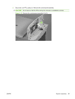
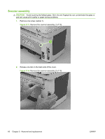
5. Push the print-cartridge door button to release the scanner assembly, and then raise the assembly until it locks open. Figure 5-17 Remove the scanner assembly (5 of 10) 6. Disconnect two FFCs (callout 3; J10 and J12) on the formatter. Remove one FFC from the ferrite (callout 4). TIP: It might be easier to thread the FFC through the ferrite by removing one screw and the ferrite (callout 4). The ferrite is not captive in the bracket and can be dislodged when you remove the bracket. Figure 5-18 Remove the scanner assembly (6 of 10) 4 3 62 Chapter 5 Removal and replacement ENWW
-
 1
1 -
2
-
3
-
4
-
5
-
6
-
7
-
8
-
9
-
10
-
11
-
12
-
13
-
14
-
15
-
16
-
17
-
18
-
19
-
20
-
21
-
22
-
23
-
24
-
25
-
26
-
27
-
28
-
29
-
30
-
31
-
32
-
33
-
34
-
35
-
36
-
37
-
38
-
39
-
40
-
41
-
42
-
43
-
44
-
45
-
46
-
47
-
48
-
49
-
50
-
51
-
52
-
53
-
54
-
55
-
56
-
57
-
58
-
59
-
60
-
61
-
62
-
63
-
64
-
65
-
66
-
67
-
68
-
69
-
70
-
71
-
72
-
 73
73 -
 74
74 -
 75
75 -
 76
76 -
 77
77 -
 78
78 -
 79
79 -
 80
80 -
 81
81 -
 82
82 -
 83
83 -
84
-
85
-
86
-
87
-
88
-
89
-
90
-
91
-
92
-
93
-
94
-
95
-
96
-
97
-
98
-
99
-
100
-
101
-
102
-
103
-
104
-
105
-
106
-
107
-
108
-
109
-
110
-
111
-
112
-
113
-
114
-
115
-
116
-
117
-
118
-
119
-
120
-
121
-
122
-
123
-
124
-
125
-
126
-
127
-
128
-
129
-
130
-
131
-
132
-
133
-
134
-
135
-
136
-
137
-
138
-
139
-
140
-
141
-
142
-
143
-
144
-
145
-
146
-
147
-
148
-
149
-
150
-
151
-
152
-
153
-
154
-
155
-
156
-
157
-
158
-
159
-
160
-
161
-
162
-
163
-
164
-
165
-
166
-
167
-
168
-
169
-
170
-
171
-
172
-
173
-
174
-
175
-
176
-
177
-
178
-
179
-
180
-
181
-
182
-
183
-
184
-
185
-
186
-
187
-
188
-
189
-
190
-
191
-
192
-
193
-
194
-
195
-
196
-
197
-
198
-
199
-
200
-
201
-
202
-
203
-
204
-
205
-
206
-
207
-
208
-
209
-
210
-
211
-
212
-
213
-
214
-
215
-
216
-
217
-
218
-
219
-
220
-
221
-
222
-
223
-
224
 |
 |
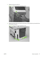
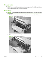
5.
Push the print-cartridge door button to release the scanner assembly, and then raise the assembly
until it locks open.
Figure 5-17
Remove the scanner assembly (5 of 10)
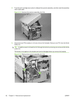
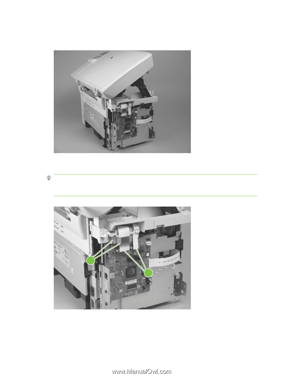
6.
Disconnect two FFCs (callout 3; J10 and J12) on the formatter. Remove one FFC from the ferrite
(callout 4).
TIP:
It might be easier to thread the FFC through the ferrite by removing one screw and the ferrite
(callout 4).
The ferrite is not captive in the bracket and can be dislodged when you remove the bracket.
Figure 5-18
Remove the scanner assembly (6 of 10)
4
3
62
Chapter 5
Removal and replacement
ENWW