HP dx7200 HP Compaq Business PC dx7200 MT Service Reference Guide, 1st edition - Page 137
Power Switch Assembly
 |
View all HP dx7200 manuals
Add to My Manuals
Save this manual to your list of manuals |
Page 137 highlights
Removal and Replacement Procedures- Slim Tower (ST) Chassis 7.14 Power Switch Assembly 1. Prepare the computer for disassembly (Section 7.1). 2. Remove the computer cover (Section 7.5). 3. Disconnect the power switch/LED cable from the system board. 4. Squeeze the switch holder retaining clips together at the front of the chassis 1 and push the switch assembly out of the chassis 2. Push the two LEDs out of the chassis 3. 5. If necessary, the LED holders may also be removed by squeezing the clips and pushing them out of the front of the chassis. To install the power switch and LEDs, reverse the removal procedure. Service Reference Guide, dx7200 390812-001 7-29
-
 1
1 -
2
-
3
-
4
-
5
-
6
-
7
-
8
-
9
-
10
-
11
-
12
-
13
-
14
-
15
-
16
-
17
-
18
-
19
-
20
-
21
-
22
-
23
-
24
-
25
-
26
-
27
-
28
-
29
-
30
-
31
-
32
-
33
-
34
-
35
-
36
-
37
-
38
-
39
-
40
-
41
-
42
-
43
-
44
-
45
-
46
-
47
-
48
-
49
-
50
-
51
-
52
-
53
-
54
-
55
-
56
-
57
-
58
-
59
-
60
-
61
-
62
-
63
-
64
-
65
-
66
-
67
-
68
-
69
-
70
-
71
-
72
-
73
-
74
-
75
-
76
-
77
-
78
-
79
-
80
-
81
-
82
-
83
-
84
-
85
-
86
-
87
-
88
-
89
-
90
-
91
-
92
-
93
-
94
-
95
-
96
-
97
-
98
-
99
-
100
-
101
-
102
-
103
-
104
-
105
-
106
-
107
-
108
-
109
-
110
-
111
-
112
-
113
-
114
-
115
-
116
-
117
-
118
-
119
-
120
-
121
-
122
-
123
-
124
-
125
-
126
-
127
-
128
-
129
-
130
-
131
-
 132
132 -
 133
133 -
 134
134 -
 135
135 -
 136
136 -
 137
137 -
 138
138 -
 139
139 -
 140
140 -
 141
141 -
 142
142 -
143
-
144
-
145
-
146
-
147
-
148
-
149
-
150
-
151
-
152
-
153
-
154
-
155
-
156
-
157
-
158
-
159
-
160
-
161
-
162
-
163
-
164
-
165
-
166
-
167
-
168
-
169
-
170
-
171
-
172
-
173
-
174
-
175
-
176
-
177
-
178
-
179
-
180
-
181
-
182
-
183
-
184
-
185
-
186
-
187
-
188
-
189
-
190
-
191
-
192
-
193
-
194
-
195
-
196
-
197
-
198
-
199
-
200
-
201
-
202
-
203
-
204
-
205
-
206
-
207
-
208
-
209
-
210
-
211
-
212
-
213
-
214
-
215
-
216
 |
 |
Service Reference Guide, dx7200
390812-001
7–29
Removal and Replacement Procedures— Slim Tower (ST) Chassis
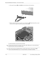
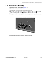
7.14 Power Switch Assembly
1. Prepare the computer for disassembly (
Section 7.1
).
2. Remove the computer cover (
Section 7.5
).
3. Disconnect the power switch/LED cable from the system board.
4. Squeeze the switch holder retaining clips together at the front of the chassis
1
and push the
switch assembly out of the chassis
2
. Push the two LEDs out of the chassis
3
.
5.
If necessary, the LED holders may also be removed by squeezing the clips and pushing them
out of the front of the chassis.
To install the power switch and LEDs, reverse the removal procedure.