HP dx7200 HP Compaq Business PC dx7200 MT Service Reference Guide, 1st edition - Page 57
PATA Device Information, 4.4 PATA Cables, 4.4.1 PATA Data Cable
 |
View all HP dx7200 manuals
Add to My Manuals
Save this manual to your list of manuals |
Page 57 highlights
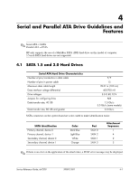
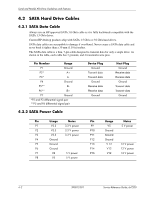
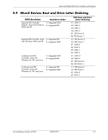
Serial and Parallel ATA Drive Guidelines and Features 4.3 PATA Device Information This information applies to optical drives in a computer having one or two SATA drive controllers and a single PATA drive controller. Only a MultiBay PATA hard drive is supported on these computers. No other PATA hard drives are supported on these models. Parallel ATA MultiBay Hard Drive Characteristics Number of pins/conductors in data cable Number of pins in power cable Maximum data cable length Data interface voltage Drive voltages Jumpers for configuring drive Data transfer rate 40/80 4 18 in (45.7 cm) 5V 5V Required 24 MB/s 4.4 PATA Cables 4.4.1 PATA Data Cable Pin Signal 1 Reset 2 Ground 3 DD7 4 DD8 5 DD6 6 DD9 7 DD5 8 DD10 9 DD4 10 DD11 11 DD3 12 DD12 13 DD2 14 DD13 Pin Signal 15 DD1 16 DD14 17 DD0 18 DD15 19 Ground 20 (Key) 21 DMARQ 22 Ground 23 DIOW 24 Ground 25 DIOR 26 Ground 27 IORDY 28 CSEL Pin Signal 29 DMAK 30 Ground 31 INTRQ 32 IOCS16 33 DA1 34 PDIAG (cable detect) 35 DA0 36 DA2 37 CS1FX 38 CS3FX 39 DASP 40 Ground Service Reference Guide, dx7200 390812-001 4-3
-
 1
1 -
2
-
3
-
4
-
5
-
6
-
7
-
8
-
9
-
10
-
11
-
12
-
13
-
14
-
15
-
16
-
17
-
18
-
19
-
20
-
21
-
22
-
23
-
24
-
25
-
26
-
27
-
28
-
29
-
30
-
31
-
32
-
33
-
34
-
35
-
36
-
37
-
38
-
39
-
40
-
41
-
42
-
43
-
44
-
45
-
46
-
47
-
48
-
49
-
50
-
51
-
 52
52 -
 53
53 -
 54
54 -
 55
55 -
 56
56 -
 57
57 -
 58
58 -
 59
59 -
 60
60 -
 61
61 -
 62
62 -
63
-
64
-
65
-
66
-
67
-
68
-
69
-
70
-
71
-
72
-
73
-
74
-
75
-
76
-
77
-
78
-
79
-
80
-
81
-
82
-
83
-
84
-
85
-
86
-
87
-
88
-
89
-
90
-
91
-
92
-
93
-
94
-
95
-
96
-
97
-
98
-
99
-
100
-
101
-
102
-
103
-
104
-
105
-
106
-
107
-
108
-
109
-
110
-
111
-
112
-
113
-
114
-
115
-
116
-
117
-
118
-
119
-
120
-
121
-
122
-
123
-
124
-
125
-
126
-
127
-
128
-
129
-
130
-
131
-
132
-
133
-
134
-
135
-
136
-
137
-
138
-
139
-
140
-
141
-
142
-
143
-
144
-
145
-
146
-
147
-
148
-
149
-
150
-
151
-
152
-
153
-
154
-
155
-
156
-
157
-
158
-
159
-
160
-
161
-
162
-
163
-
164
-
165
-
166
-
167
-
168
-
169
-
170
-
171
-
172
-
173
-
174
-
175
-
176
-
177
-
178
-
179
-
180
-
181
-
182
-
183
-
184
-
185
-
186
-
187
-
188
-
189
-
190
-
191
-
192
-
193
-
194
-
195
-
196
-
197
-
198
-
199
-
200
-
201
-
202
-
203
-
204
-
205
-
206
-
207
-
208
-
209
-
210
-
211
-
212
-
213
-
214
-
215
-
216
 |
 |