HP dx7200 HP Compaq Business PC dx7200 MT Service Reference Guide, 1st edition - Page 59
SATA SMART Drives, 4.7 Drive Capacities, 4.8 SATA BIOS, Drive/Partition Capacity Limits
 |
View all HP dx7200 manuals
Add to My Manuals
Save this manual to your list of manuals |
Page 59 highlights
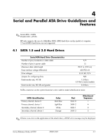
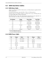
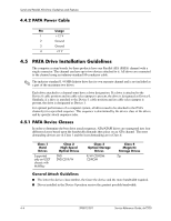
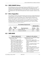
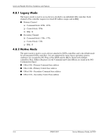
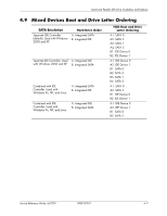
Serial and Parallel ATA Drive Guidelines and Features 4.6 SATA SMART Drives The Self Monitoring Analysis and Recording Technology (SMART) SATA drives for the HP Personal Computers have built-in drive failure prediction that warns the user or network administrator of an impending failure or crash of the hard drive. The SMART drive tracks fault prediction and failure indication parameters such as reallocated sector count, spin retry count, and calibration retry count. If the drive determines that a failure is imminent, it generates a fault alert. 4.7 Drive Capacities The combination of the file system and the operating system used in the computer determines the maximum usable size of a drive partition. A drive partition is the largest segment of a drive that may be properly accessed by the operating system. A single hard drive may therefore be subdivided into a number of unique drive partitions in order to make use of all of its space. Because of the differences in the way that drive sizes are calculated, the size reported by the operating system may differ from that marked on the hard drive or listed in the computer specification. Drive size calculations by drive manufacturers are bytes to the base 10 while calculations by Microsoft are bytes to the base 2. Drive/Partition Capacity Limits File System FAT 32 NTFS Controller Type ATA ATA Operating System Windows 2000/ XP Windows NT/2000/XP Maximum Size Partition 32 GB 2 TB Drive 128 PB 128 PB 4.8 SATA BIOS Windows 2000 and XP Enhanced Mode (default BIOS Setting) -Separate IDE controller • PATA Controller in Legacy Mode - Device 0 is accessible as Device 0 of PATA controller's Primary Channel - Device 1 is accessible as Device 1of PATA controller's Primary Channel • SATA Controller in Native Mode - SATA 0 is accessible as Device 0 of SATA controller's Primary Channel - SATA 1 is accessible as Device 0 of SATA controller's Secondary Channel SATA 2 is accessible as Device 1of SATA controller's Primary Channel - SATA 3 is accessible as Device 1 of SATA controller's Secondary Channel Windows 9x, NT, and Linux Compatibility Mode (non-default BIOS Setting) -Combined IDE controller • PATA Controller in Legacy Mode - Device 0 is accessible as Device 0 of the combined controller's Secondary Channel - Device 1 is accessible as Device 1of the combined controller's Secondary Channel • SATA Controller in Legacy Mode - SATA 0 is accessible as Device 0 of the combined controller's Primary Channel - SATA 1 is inaccessible - SATA 2 is accessible as device 1 of the combined controller's Primary Channel - SATA 3 is inaccessible Service Reference Guide, dx7200 390812-001 4-5
-
 1
1 -
2
-
3
-
4
-
5
-
6
-
7
-
8
-
9
-
10
-
11
-
12
-
13
-
14
-
15
-
16
-
17
-
18
-
19
-
20
-
21
-
22
-
23
-
24
-
25
-
26
-
27
-
28
-
29
-
30
-
31
-
32
-
33
-
34
-
35
-
36
-
37
-
38
-
39
-
40
-
41
-
42
-
43
-
44
-
45
-
46
-
47
-
48
-
49
-
50
-
51
-
52
-
53
-
 54
54 -
 55
55 -
 56
56 -
 57
57 -
 58
58 -
 59
59 -
 60
60 -
 61
61 -
 62
62 -
 63
63 -
 64
64 -
65
-
66
-
67
-
68
-
69
-
70
-
71
-
72
-
73
-
74
-
75
-
76
-
77
-
78
-
79
-
80
-
81
-
82
-
83
-
84
-
85
-
86
-
87
-
88
-
89
-
90
-
91
-
92
-
93
-
94
-
95
-
96
-
97
-
98
-
99
-
100
-
101
-
102
-
103
-
104
-
105
-
106
-
107
-
108
-
109
-
110
-
111
-
112
-
113
-
114
-
115
-
116
-
117
-
118
-
119
-
120
-
121
-
122
-
123
-
124
-
125
-
126
-
127
-
128
-
129
-
130
-
131
-
132
-
133
-
134
-
135
-
136
-
137
-
138
-
139
-
140
-
141
-
142
-
143
-
144
-
145
-
146
-
147
-
148
-
149
-
150
-
151
-
152
-
153
-
154
-
155
-
156
-
157
-
158
-
159
-
160
-
161
-
162
-
163
-
164
-
165
-
166
-
167
-
168
-
169
-
170
-
171
-
172
-
173
-
174
-
175
-
176
-
177
-
178
-
179
-
180
-
181
-
182
-
183
-
184
-
185
-
186
-
187
-
188
-
189
-
190
-
191
-
192
-
193
-
194
-
195
-
196
-
197
-
198
-
199
-
200
-
201
-
202
-
203
-
204
-
205
-
206
-
207
-
208
-
209
-
210
-
211
-
212
-
213
-
214
-
215
-
216
 |
 |
