HP dx7200 HP Compaq Business PC dx7200 MT Service Reference Guide, 1st edition - Page 58
PATA Power Cable, 4.5 PATA Drive Installation Guidelines, 4.5.1 PATA Device Classes
 |
View all HP dx7200 manuals
Add to My Manuals
Save this manual to your list of manuals |
Page 58 highlights
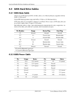
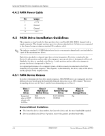
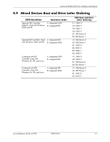
Serial and Parallel ATA Drive Guidelines and Features 4.4.2 PATA Power Cable Pin Usage 1 +12 V 2 Ground 3 Ground 4 +5 V 4.5 PATA Drive Installation Guidelines The computer system boards for these products have one Parallel ATA (PATA) channel with a single connector. The channel can have up to two devices attached to it. All drives are connected to the channel using an industry-standard 80-conductor cable. ✎ The industry-standard 1.44 MB diskette drive has its own separate channel and is not included as a part of the maximum two drives. Each drive attached to a channel must have a drive designation. If a drive is attached to the Device 0 cable position and its cable-select jumper is present, the drive is designated as Device 0. Similarly, if a drive is attached to the Device 1 cable position and its cable-select jumper is present, the drive is designated as Device 1. For optimal performance of a computer system, all drives need to be attached to the PATA channel(s) in a specified sequence. This sequence is determined by the device class of the drives and by specific attach sequence rules. 4.5.1 PATA Device Classes In order to determine the best drive attach sequence, ATA/ATAPI drives are segregated into four different classes based upon the bandwidth demands they place on an ATA channel. The most demanding devices are in Class 1 and the least demanding are in Class 4. Class 1 Hard Drives Supported only on USDT chassis with MultiBay Class 2 High Speed Optical Drives DVD DVD-CD R/W Class 3 Optical Storage Drives R/W CD-ROM CD-ROM Class 4 Magnetic Storage Drives Zip General Attach Guidelines ■ The lower the device class number, the faster the device and the more bandwidth required. ■ Drives installed in the Device 0 position receive the greatest possible bandwidth. 4-4 390812-001 Service Reference Guide, dx7200
-
 1
1 -
2
-
3
-
4
-
5
-
6
-
7
-
8
-
9
-
10
-
11
-
12
-
13
-
14
-
15
-
16
-
17
-
18
-
19
-
20
-
21
-
22
-
23
-
24
-
25
-
26
-
27
-
28
-
29
-
30
-
31
-
32
-
33
-
34
-
35
-
36
-
37
-
38
-
39
-
40
-
41
-
42
-
43
-
44
-
45
-
46
-
47
-
48
-
49
-
50
-
51
-
52
-
 53
53 -
 54
54 -
 55
55 -
 56
56 -
 57
57 -
 58
58 -
 59
59 -
 60
60 -
 61
61 -
 62
62 -
 63
63 -
64
-
65
-
66
-
67
-
68
-
69
-
70
-
71
-
72
-
73
-
74
-
75
-
76
-
77
-
78
-
79
-
80
-
81
-
82
-
83
-
84
-
85
-
86
-
87
-
88
-
89
-
90
-
91
-
92
-
93
-
94
-
95
-
96
-
97
-
98
-
99
-
100
-
101
-
102
-
103
-
104
-
105
-
106
-
107
-
108
-
109
-
110
-
111
-
112
-
113
-
114
-
115
-
116
-
117
-
118
-
119
-
120
-
121
-
122
-
123
-
124
-
125
-
126
-
127
-
128
-
129
-
130
-
131
-
132
-
133
-
134
-
135
-
136
-
137
-
138
-
139
-
140
-
141
-
142
-
143
-
144
-
145
-
146
-
147
-
148
-
149
-
150
-
151
-
152
-
153
-
154
-
155
-
156
-
157
-
158
-
159
-
160
-
161
-
162
-
163
-
164
-
165
-
166
-
167
-
168
-
169
-
170
-
171
-
172
-
173
-
174
-
175
-
176
-
177
-
178
-
179
-
180
-
181
-
182
-
183
-
184
-
185
-
186
-
187
-
188
-
189
-
190
-
191
-
192
-
193
-
194
-
195
-
196
-
197
-
198
-
199
-
200
-
201
-
202
-
203
-
204
-
205
-
206
-
207
-
208
-
209
-
210
-
211
-
212
-
213
-
214
-
215
-
216
 |
 |
