HP dx7200 HP Compaq Business PC dx7200 MT Service Reference Guide, 1st edition - Page 210
Channel B., Description, Socket Color
 |
View all HP dx7200 manuals
Add to My Manuals
Save this manual to your list of manuals |
Page 210 highlights
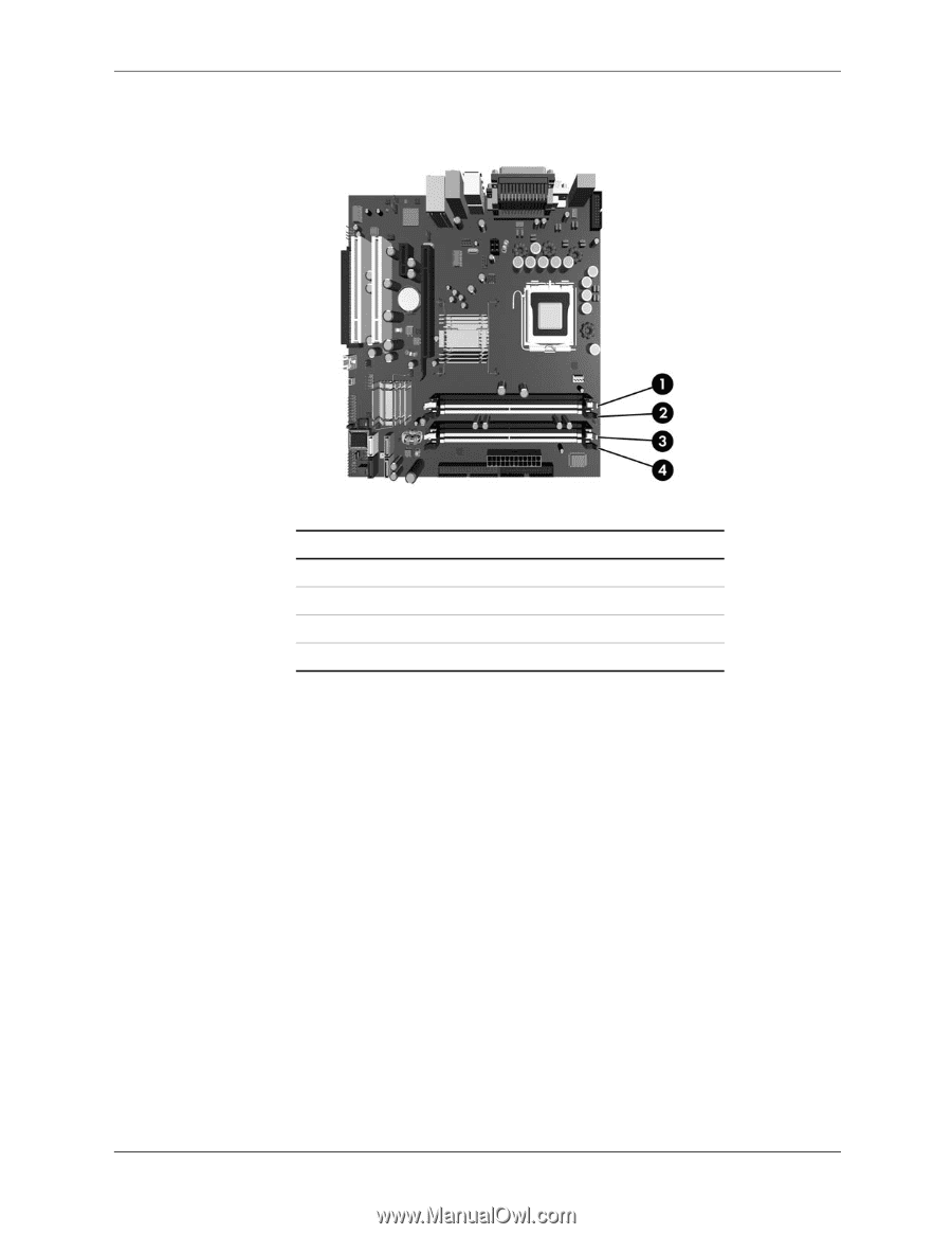
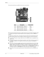
Memory The system board shown may differ from the one in your product. Item 1 2 3 4 Description DIMM socket XMM1, Channel A DIMM socket XMM2, Channel A DIMM socket XMM3, Channel B DIMM socket XMM4, Channel B Socket Color Black White Black White The system will automatically operate in single channel mode, dual channel Asymmetric mode, or a a higher-performing dual channel Interleaved mode, depending on how the DIMMs are installed. To identify the operating mode, run Computer Setup and select the System Information menu item. The operating memory mode will appear in the line showing the system total memory. ■ The system will operate in single channel mode if the DIMM sockets are populated in one channel only. ■ The system will operate in dual channel Asymmetric mode if the total memory capacity of the DIMMs in Channel A is not equal to the total memory capacity of the DIMMs in Channel B. ■ The system will operate in a higher-performing dual channel Interleaved mode if the total memory capacity of the DIMMs in Channel A is equal to the total memory capacity of the DIMMs in Channel B. However, the technology and device width can vary between the channels, For example, if Channel A is populated with two 256 MB DIMMS and Channel B is populated with one 512 MB DIMM, the system will operate in Interleaved mode. ■ In any mode, the maximum operational speed is determined by the slowest DIMM in the system. F-2 390812-001 Service Reference Guide, dx7200
-
 1
1 -
2
-
3
-
4
-
5
-
6
-
7
-
8
-
9
-
10
-
11
-
12
-
13
-
14
-
15
-
16
-
17
-
18
-
19
-
20
-
21
-
22
-
23
-
24
-
25
-
26
-
27
-
28
-
29
-
30
-
31
-
32
-
33
-
34
-
35
-
36
-
37
-
38
-
39
-
40
-
41
-
42
-
43
-
44
-
45
-
46
-
47
-
48
-
49
-
50
-
51
-
52
-
53
-
54
-
55
-
56
-
57
-
58
-
59
-
60
-
61
-
62
-
63
-
64
-
65
-
66
-
67
-
68
-
69
-
70
-
71
-
72
-
73
-
74
-
75
-
76
-
77
-
78
-
79
-
80
-
81
-
82
-
83
-
84
-
85
-
86
-
87
-
88
-
89
-
90
-
91
-
92
-
93
-
94
-
95
-
96
-
97
-
98
-
99
-
100
-
101
-
102
-
103
-
104
-
105
-
106
-
107
-
108
-
109
-
110
-
111
-
112
-
113
-
114
-
115
-
116
-
117
-
118
-
119
-
120
-
121
-
122
-
123
-
124
-
125
-
126
-
127
-
128
-
129
-
130
-
131
-
132
-
133
-
134
-
135
-
136
-
137
-
138
-
139
-
140
-
141
-
142
-
143
-
144
-
145
-
146
-
147
-
148
-
149
-
150
-
151
-
152
-
153
-
154
-
155
-
156
-
157
-
158
-
159
-
160
-
161
-
162
-
163
-
164
-
165
-
166
-
167
-
168
-
169
-
170
-
171
-
172
-
173
-
174
-
175
-
176
-
177
-
178
-
179
-
180
-
181
-
182
-
183
-
184
-
185
-
186
-
187
-
188
-
189
-
190
-
191
-
192
-
193
-
194
-
195
-
196
-
197
-
198
-
199
-
200
-
201
-
202
-
203
-
204
-
 205
205 -
 206
206 -
 207
207 -
 208
208 -
 209
209 -
 210
210 -
 211
211 -
 212
212 -
 213
213 -
 214
214 -
 215
215 -
216
 |
 |