Honeywell NX4S1 Installation Guide - Page 17
NetAXS™ Access Control Unit
 |
View all Honeywell NX4S1 manuals
Add to My Manuals
Save this manual to your list of manuals |
Page 17 highlights
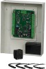
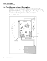
NetAXS™ NX4S1 Installation Panel Components and Descriptions Note: Maintain at least a .25-inch distance between the non-power limited wiring battery backup/charger wiring) and all other wiring, which is power-limited Class 2 wiring. 3.1 NetAXS™ Access Control Unit The NetAXS™ panel is a four-reader board that controls up to four doors by providing up to 14 inputs and 8 outputs. The NetAXS™ panel may be used as a stand-alone panel with independent card and transaction storage or, with a host software upgrade, as a fully monitored online access control device. The NetAXS™ panel also supports up to 30 downstream panels in a variety of network configurations. See Communications, page 16, for descriptions and illustrations. Fourteen inputs are capable of four state supervision: Normal, Alarm, Short and Open. Eight inputs are used as door control with one input used for request to exit on each door and one input used for door status on each door. Supervised inputs for Tamper, External Power Fail and four Reader Tampers are supplied as well, and they can be used as additional inputs when not required for their default purpose. Caution: The NetAXS™ board must not be used to power locks. Only through the relay board can the common power supply be used for the NetAXS™ and locking devices. Real-Time Clock Protection The panel RTC is backed up using a super capacitor. The super capacitor will power the real-time clock for one week in the absence of primary power or backup battery. Memory Protection The NetAXS™ panel continuously saves database and event information in non-volatile FLASH memory. This activity prevents the panel from losing data when power is lost. Reader and AUX Power Reader power is supplied within the range of 11.2 VDC and 12.4 VDC with a maximum current of 600 mA. AUX power is supplied within the range of 10.5 VDC and 12.4 VDC with a maximum current of 500mA. The current can be distributed throughout the Reader Power or AUX Power in any configuration as long as the maximum draw is less than 600 mA: Reader 1 + Reader 2 + Reader 3 + Reader 4 + AUX Power < 600 mA. Caution: AUX Power must not be used to power locks. For NetAXS™ maximum current draw, refer to Hardware Specifications, page 44. NetAXS Access Control Unit NX4S1 Installation Guide, Document 800-00008, Revision A 7
-
 1
1 -
2
-
3
-
4
-
5
-
6
-
7
-
8
-
9
-
10
-
11
-
 12
12 -
 13
13 -
 14
14 -
 15
15 -
 16
16 -
 17
17 -
 18
18 -
 19
19 -
 20
20 -
 21
21 -
 22
22 -
23
-
24
-
25
-
26
-
27
-
28
-
29
-
30
-
31
-
32
-
33
-
34
-
35
-
36
-
37
-
38
-
39
-
40
-
41
-
42
-
43
-
44
-
45
-
46
-
47
-
48
-
49
-
50
-
51
-
52
-
53
-
54
-
55
-
56
-
57
-
58
-
59
-
60
-
61
-
62
-
63
-
64
-
65
-
66
-
67
-
68
-
69
-
70
-
71
-
72
-
73
 |
 |