Honeywell NX4S1 Installation Guide - Page 57
NX4S1 Wiring Diagram
 |
View all Honeywell NX4S1 manuals
Add to My Manuals
Save this manual to your list of manuals |
Page 57 highlights
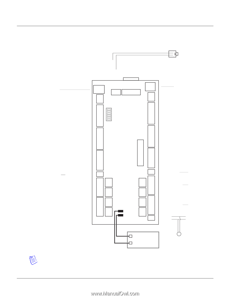
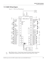
7.10 NX4S1 Wiring Diagram Figure 33: NX4S1 Panel Wiring Diagram NetAXS™ NX4S1 Installation Hardware Specifications Tamper Switch Panel Tamper/IN 14 Common ACFAIL/IN 13 RESERVED FOR FUTURE USE RS-232 * Ethernet* Expansion RS-485* 12VDC * Inputs * Host RS-485* Reader 3* Reader 1* Reader 4* Reader 2* Door 3/4 AC Output 7/8* Output 5/6 * Aux Outputs* 12VDC* Inputs* Door 1/2 } } }} } } } Host RS485+ Host RS485Common LED/OUT 11 D0 D1 Common +12VDC Tamper/IN 9 Buzzer/OUT 15 LED/OUT 12 D0 D1 Common +12VDC Tamper/IN 10 Buzzer/OUT 16 Door1 REX/IN 1 Common Door1 Status/IN 2 Door2 REX/IN 3 Common Door2 Status/IN 4 Aux + 12VDC Aux Common Relay 1 N.O. Relay 1 Com Relay 1 N.C. Relay 2 N.O. Relay 2 Com Relay 2 N.C. Relay 3 N.O. Relay 3 Com Relay 3 N.C. Relay 4 N.O. Relay 4 Com Relay 4 N.C. Ethernet TB8 TB9 TB7 DIP switches 6 TB6 1 RS-232 TB10 TB11 TB5 XPORT TB12 TB13 TB4 TB14 TB3 TB2 TB15 TB16 TB1 J20 (+) J24 (-) TB17 } Expansion RS485-/B Expansion RS485+/A } Buzzer/OUT 17 Tamper/IN 11 +12VDC Common D1 D0 LED/OUT 13 } Buzzer/OUT 16 Tamper/IN 12 +12VDC Common D1 D0 LED/OUT 14 } DR3 REX/IN 5 Common DR3 Status/IN 6 DR4 REX/IN 7 Common DR4 Status/IN 8 } Aux Common Aux + 12VDC } Relay 5 N.C. Relay 5 Com Relay 5 N.O. Relay 6 N.C. Relay 6 Com Relay 6 N.O. } Relay 7 N.C. Relay 7 Com Relay 7 N.O. Relay 8 N.C. Relay 8 Com Relay 8 N.O. AC/DC AC/DC + } Door 1/2 Aux Door 3/4 Outputs* _ Battery CASIL CA1270 + HAS 3-000066 12VDC, 7AHr Power LED Note: Maintain at least a .25-inch distance between the non-power limited wiring (battery backup/charger wiring) and all other wiring, which is power-limited Class 2 wiring. Input * NetAXS Access Control Unit NX4S1 Installation Guide, Document 800-00008, Revision A 47
-
 1
1 -
2
-
3
-
4
-
5
-
6
-
7
-
8
-
9
-
10
-
11
-
12
-
13
-
14
-
15
-
16
-
17
-
18
-
19
-
20
-
21
-
22
-
23
-
24
-
25
-
26
-
27
-
28
-
29
-
30
-
31
-
32
-
33
-
34
-
35
-
36
-
37
-
38
-
39
-
40
-
41
-
42
-
43
-
44
-
45
-
46
-
47
-
48
-
49
-
50
-
51
-
 52
52 -
 53
53 -
 54
54 -
 55
55 -
 56
56 -
 57
57 -
 58
58 -
 59
59 -
 60
60 -
 61
61 -
 62
62 -
63
-
64
-
65
-
66
-
67
-
68
-
69
-
70
-
71
-
72
-
73
 |
 |