Honeywell NX4S1 Installation Guide - Page 33
Jumper Settings, Downstream I/O - installation manual
 |
View all Honeywell NX4S1 manuals
Add to My Manuals
Save this manual to your list of manuals |
Page 33 highlights
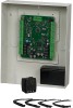
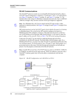
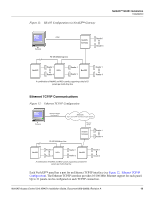
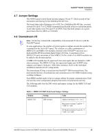
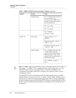
NetAXS™ NX4S1 Installation Installation 4.7 Jumper Settings The NX4S1 panel control board includes jumpers 36 and 37, which set end-of-line termination and biasing for the Multidrop RS-485 line. The board ships with all jumpers set to OFF. For a Multidrop RS-485 line, you must set both J36 and J37 to CLOSED (terminated and biased) at the two end-point panels. At all other panels, leave J36 and J37 at OPEN. Note that both jumpers on a given panel must either be OPEN or CLOSED. 4.8 Downstream I/O Note: UL has not evaluated the compatibility of downstream I/O devices with the NetAXS™ panel. In some applications, the number of system inputs or outputs exceeds the number that is standard on the NetAXS™ panel. The solution is to add a combination of MIRO-2/16 and MIRO-32/0 modules external to the NetAXS™ enclosure on a dedicated RS-485 Downstream Input/Output (I/O) bus. A maximum of two MIRO-32/0 and a maximum of four MIRO-2/16 for a total of six MIRO modules can be added to the downstream bus. A MIRO-32/0 module has 32 supervised, four-state inputs that are limited to 1,000 ohms resistance. The MIRO-2/16 has two supervised inputs and 16 SPDT relay outputs; each input is limited to 1,000 ohms resistance. Refer to the individual installation manuals for I/O wiring details. The downstream I/O bus is wired into the NetAXS™ TB10 terminal block. The downstream bus has a fixed baud rate and communicates to the MIRO modules using a polling technique. Each MIRO module needs to have a unique address for proper communication. Each one also has some configuration jumpers that need to be positioned correctly. The following table lists the DIP switch and jumper settings for the MIRO 32/0 and 2/16 modules. Table 4 MIRO 32/0 DIP Switch and Jumper Settings Module Setting Value MIRO 32/0 DIP switches Address (switches 1-6) - 1 or 2 Baud rate (switches 7 and 8) - 7 = OFF, 8 = ON OP Mode (switches 9 and 10) - 9 = OFF, 10 = OFF NetAXS Access Control Unit NX4S1 Installation Guide, Document 800-00008, Revision A 23
-
 1
1 -
2
-
3
-
4
-
5
-
6
-
7
-
8
-
9
-
10
-
11
-
12
-
13
-
14
-
15
-
16
-
17
-
18
-
19
-
20
-
21
-
22
-
23
-
24
-
25
-
26
-
27
-
 28
28 -
 29
29 -
 30
30 -
 31
31 -
 32
32 -
 33
33 -
 34
34 -
 35
35 -
 36
36 -
 37
37 -
 38
38 -
39
-
40
-
41
-
42
-
43
-
44
-
45
-
46
-
47
-
48
-
49
-
50
-
51
-
52
-
53
-
54
-
55
-
56
-
57
-
58
-
59
-
60
-
61
-
62
-
63
-
64
-
65
-
66
-
67
-
68
-
69
-
70
-
71
-
72
-
73
 |
 |