Honeywell NX4S1 Installation Guide - Page 19
Installation
 |
View all Honeywell NX4S1 manuals
Add to My Manuals
Save this manual to your list of manuals |
Page 19 highlights
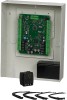
NetAXS™ NX4S1 Installation Installation 4.0 Installation Perform the following steps to install the NX4S1 panel: Warning: Use a static strap whenever touching the panel to ensure protection from Electrostatic Discharge (ESD). 1. Review the panel layout, cable runs, and power needs. 2. Mount the enclosure at the proper location on the wall. Use appropriate anchors for the mounting material. 3. Run all I/O wires to the enclosure, and properly mark each wire for its use. 4. Run appropriate length of two-wire, 18 AWG shielded cable from the wall transformer to the enclosure. The AC input must be supplied at 16.5 VAC utilizing one of the following UL-listed, 50 VA, Class 2 transformers: Basler Electric Model BE156250CAA0004, M&G Electronics Model MGT1650, or Honeywell Access Systems part number X-4. The AC voltage is non-polarized and connects to TB17-1 and TB17-2. Caution: Do not plug in the wall transformer at this time, and do not connect to a receptacle controlled by a switch. 5. Run a 14 AWG green wire from the enclosure to a proper earth ground. 6. Remove each terminal plug one at a time to wire the properly labeled cables. See the wiring diagram (Figure 33 on page 47). Leave enough shield drain length to secure to the grounding stud. Also, maintain a distance of at least .25 inches between the non-power limited wiring (battery backup/charger wiring) and all other wiring, which is power-limited Class 2 wiring. Caution: Do not plug in the wall transformer at this time. 7. Connect the shield and the green earth ground to the enclosure's grounding studs (see Figure 1 on page 6) for the location of the enclosure's grounding studs). 8. Set DIP switch settings for the panel address (Table 3 on page 22), and set J36 and J37 for communication termination and biasing (see "System Configuration" on page 26 and "Jumper Settings" on page 23). 9. Check all wiring at this time. Caution: Improper wiring can cause damage to the NetAXS™ panel at power up resulting in a loss of warranty. 10.Power up the panel. The power-up sequence may take up to two minutes, after which the RUN LED blinks green. The RUN LED is located near Terminal Block (TB) 8. After the power-up sequence, check the LEDs to be sure the panel has powered up properly (see "LED Operation" on page 42). 11.Configure the panel by following the instructions in the NetAXS™ Access Control Unit User's Guide. 12.If you are using a battery backup function, place the 7 A-Hr battery in the enclosure. 13.Attach the positive (red) Power Supply-to-Battery cable to the positive (red) battery terminal. NetAXS Access Control Unit NX4S1 Installation Guide, Document 800-00008, Revision A 9
-
 1
1 -
2
-
3
-
4
-
5
-
6
-
7
-
8
-
9
-
10
-
11
-
12
-
13
-
 14
14 -
 15
15 -
 16
16 -
 17
17 -
 18
18 -
 19
19 -
 20
20 -
 21
21 -
 22
22 -
 23
23 -
 24
24 -
25
-
26
-
27
-
28
-
29
-
30
-
31
-
32
-
33
-
34
-
35
-
36
-
37
-
38
-
39
-
40
-
41
-
42
-
43
-
44
-
45
-
46
-
47
-
48
-
49
-
50
-
51
-
52
-
53
-
54
-
55
-
56
-
57
-
58
-
59
-
60
-
61
-
62
-
63
-
64
-
65
-
66
-
67
-
68
-
69
-
70
-
71
-
72
-
73
 |
 |