Honeywell NX4S1 Installation Guide - Page 24
Reader Wiring, Supervised Input Wiring
 |
View all Honeywell NX4S1 manuals
Add to My Manuals
Save this manual to your list of manuals |
Page 24 highlights
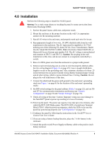
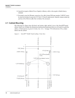
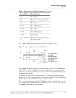
NetAXS™ NX4S1 Installation Installation 4.2 Reader Wiring Each reader port supports a single 12-volt reader with Wiegand output format. Power to the readers is shared with the AUX Power ports TB3 and TB14. The maximum power draw is 600 mA for readers and AUX Power combined. To fully utilize each reader port, a shielded 7-conductor cable (18-22 AWG) is required. If the optional reader buzzer feature is not needed, you can use the standard six-conductor cable (HAS part number NC1861-BL). The cable shield should be grounded at the panel only. Grounding at both ends can cause ground loops which can be disruptive. The maximum recommended length of wiring is 500 feet per reader. Table 1 Reader Wiring Terminal Wire Color Wiegand Reader TB5-1, 6-1, 11-1, 12-1 Brown LED Control TB5-2 6-2, 11-2, 12-2 Green Wiegand Data 0 or Data TB5-3, 6-3, 11-3, 12-3 White Wiegand Data 1 or Clock TB5-4, 6-4, 11-4, 12-4 Black Common TB5-5, 6-5, 11-5, 12-5 Red 12VDC Power TB5-6, 6-6, 11-6, 12-6 Variable Tamper TB5-7, 6-7, 11-7, 12-7 Variable Buzzer 4.3 Supervised Input Wiring The supervised inputs are located on TB4 and TB13 (Figure 7 on page 15). Input 1 through Input 8 may be configured for normally open or normally closed contacts as supervised or non-supervised. Inputs 13 and 14 are on TB8. All eight inputs have default functions, but they can be configured for general purpose inputs. The following table identifies the default function for each terminal position. Table 2 Default Supervised Input Assignments Terminal Position Default Function TB4-1 Door 1 REX (Egress) TB4-3 Door 1 Status TB4-4 Door 2 REX (Egress) 14 www.honeywell.com
-
 1
1 -
2
-
3
-
4
-
5
-
6
-
7
-
8
-
9
-
10
-
11
-
12
-
13
-
14
-
15
-
16
-
17
-
18
-
 19
19 -
 20
20 -
 21
21 -
 22
22 -
 23
23 -
 24
24 -
 25
25 -
 26
26 -
 27
27 -
 28
28 -
 29
29 -
30
-
31
-
32
-
33
-
34
-
35
-
36
-
37
-
38
-
39
-
40
-
41
-
42
-
43
-
44
-
45
-
46
-
47
-
48
-
49
-
50
-
51
-
52
-
53
-
54
-
55
-
56
-
57
-
58
-
59
-
60
-
61
-
62
-
63
-
64
-
65
-
66
-
67
-
68
-
69
-
70
-
71
-
72
-
73
 |
 |