Honeywell NX4S1 Installation Guide - Page 34
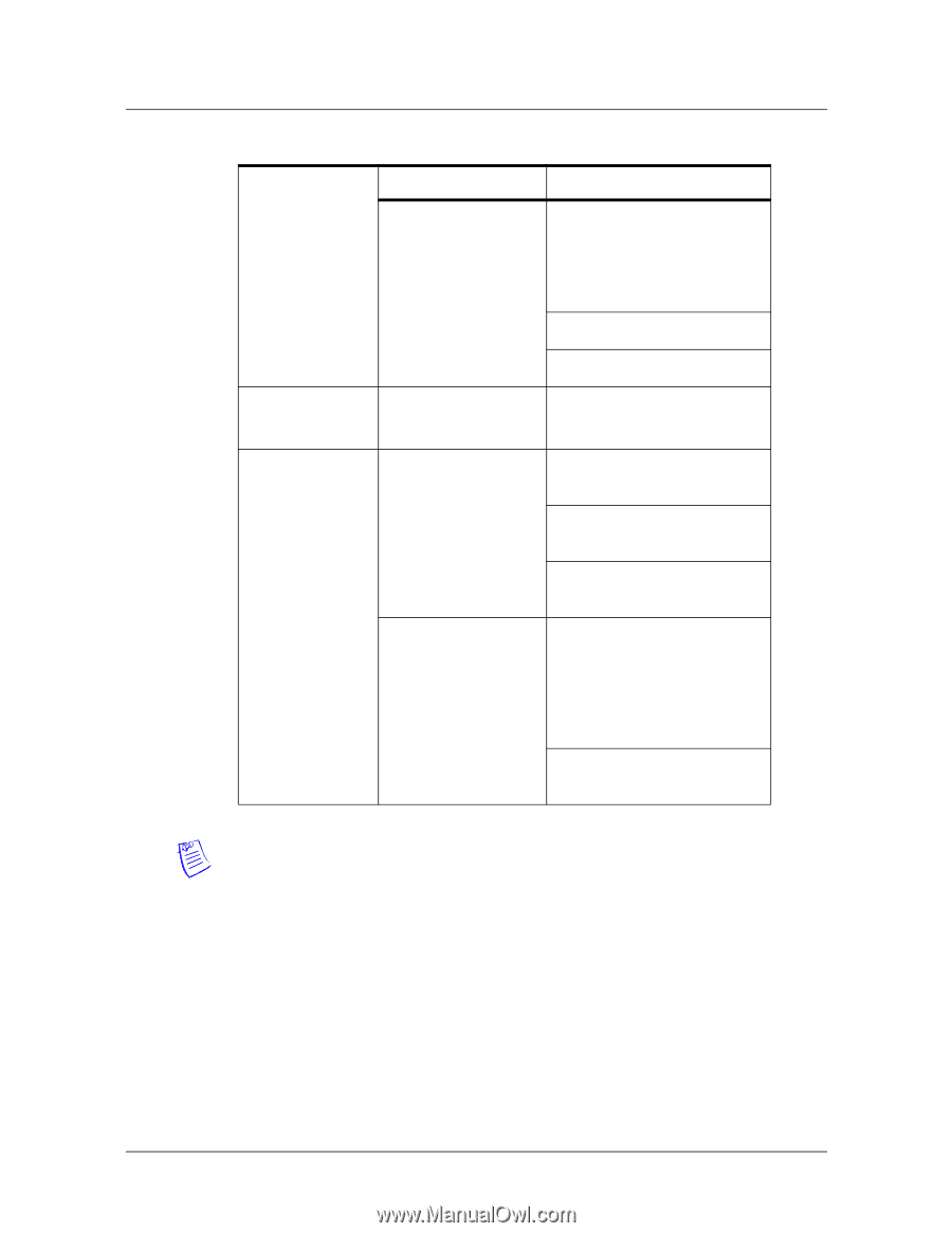
Table 4, MIRO 32/0 DIP Switch and Jumper Settings
 |
View all Honeywell NX4S1 manuals
Add to My Manuals
Save this manual to your list of manuals |
Page 34 highlights
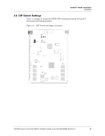
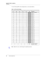
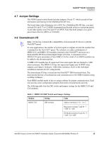
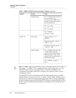
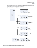
NetAXS™ NX4S1 Installation Installation Table 4 MIRO 32/0 DIP Switch and Jumper Settings (continued) Module Setting Value Jumper settings JP1 - CLOSED (if the module is the last module on the downstream bus), OPEN (if the module is not the last module on the downstream bus) JP2 - any setting JP3 - any setting JP4 - NORMAL (Positions 1 and 2) MIRO 2/16 DIP switches Address (switches 1-6) - 3 through 6 Baud rate (switches 7 and 8) - 7 = OFF, 8 = ON OP Mode (switches 9 and 10) - 9 = OFF, 10 = OFF Jumper settings JP1 - CLOSED, positions 2 and 3 (if the module is the last module on the downstream bus); OPEN, positions 1 and 2 (if the module is not the last module on the downstream bus) JP2 - NORMAL, positions 1 and 2 Note: If a MIRO 32/0 is not required in a system, start addressing the 2/16 modules at DIP switch 3. If a MIRO 32/0 is configured with an address other than 1 or 2, the NetAXS™ panel will not communicate with it. Likewise, if a MIRO 2/16 is configured with an address other than 3 through 6, the NetAXS™ panel will not communicate with it. The NetAXS™ board is not intended to provide either module power or module output load power for downstream I/O. A separate 24VDC supply should be used to provide power to all downstream modules and output loads. For some installations, the noise immunity improves if the NetAXS™ common is connected to the 24 VDC Return wiring for the downstream modules. This connection is not needed for most installations. 24 www.honeywell.com
-
 1
1 -
2
-
3
-
4
-
5
-
6
-
7
-
8
-
9
-
10
-
11
-
12
-
13
-
14
-
15
-
16
-
17
-
18
-
19
-
20
-
21
-
22
-
23
-
24
-
25
-
26
-
27
-
28
-
 29
29 -
 30
30 -
 31
31 -
 32
32 -
 33
33 -
 34
34 -
 35
35 -
 36
36 -
 37
37 -
 38
38 -
 39
39 -
40
-
41
-
42
-
43
-
44
-
45
-
46
-
47
-
48
-
49
-
50
-
51
-
52
-
53
-
54
-
55
-
56
-
57
-
58
-
59
-
60
-
61
-
62
-
63
-
64
-
65
-
66
-
67
-
68
-
69
-
70
-
71
-
72
-
73
 |
 |