Honeywell NX4S1 Installation Guide - Page 7

Igures

Page 7 highlights

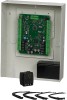
LIST OF FIGURES Figure 1: NX4S1 Panel Components 6 Figure 2: NetAXS™ NX4S1 Panel Cabinet, Front View 10 Figure 3: NetAXS™ NX4S1 Panel Cabinet, Top View 11 Figure 4: NetAXS™ NX4S1 Panel Cabinet, Bottom View 11 Figure 5: NetAXS™ Panel Cabinet, Left View 12 Figure 6: NetAXS™ NX4S1Panel Cabinet, Right View 13 Figure 7: Typical Supervised Input Wiring Diagram 15 Figure 8: RJ-45 Serial Port 17 Figure 9: RS-232 Configuration 17 Figure 10: RS-485 Configuration via N-485-PCI-2 or PCI-3 18 Figure 11: RS-485 Configuration via NetAXS™ Gateway 19 Figure 12: Ethernet TCP/IP Configuration 19 Figure 13: Ethernet MAC Address Location 20 Figure 14: DIP Switch and Jumper Locations 21 Figure 15: Default Downstream I/O Configuration with Wiring 25 Figure 16: RS-485 Connection via PCI-2 26 Figure 17: RS-485 Connection via NetAXS 27 Figure 18: RS-485 Connection via NetAXS™ with Multidrop Panels at Both Ends 28 Figure 19: RS-485 Connection via PCI-2 with Multidrop Panels at Both Ends ........ 29 Figure 20: RS-232 Connection 30 Figure 21: Ethernet Connection 31 Figure 22: LANSRLU1 Connection 32 Figure 23: RS-485 Short Haul Modem Connection via PCI-2 33 Figure 24: RS-485 Short Haul Modem Connection via NetAXS 34 Figure 25: RS-232 Short Haul Modem Connection 35 Figure 26: M-56K Dial-up Modem, RS-485 Connection via Hub 36 Figure 27: M-56K Dial-up Modem, RS-485 Connection via NetAXS 37 Figure 28: Fiber Converter to RS-485 Connection via PCI-2 38 Figure 29: Fiber Converter to RS-485 Connection via NetAXS 39 Figure 30: N-485-PCI-2/NetAXS™ Access Controller Panel Connection Detail ..... 40 Figure 31: NetAXS™/NetAXS™ Access Controller Panel Connection Detail ......... 41 Figure 32: System, Relay and Power LEDs 42 Figure 33: NX4S1 Panel Wiring Diagram 47 NetAXS Access Control Unit NX4S1 Installation Guide, Document 800-00008, Revision A vii

  • 1
  • 2
  • 3
  • 4
  • 5
  • 6
  • 7
  • 8
  • 9
  • 10
  • 11
  • 12
  • 13
  • 14
  • 15
  • 16
  • 17
  • 18
  • 19
  • 20
  • 21
  • 22
  • 23
  • 24
  • 25
  • 26
  • 27
  • 28
  • 29
  • 30
  • 31
  • 32
  • 33
  • 34
  • 35
  • 36
  • 37
  • 38
  • 39
  • 40
  • 41
  • 42
  • 43
  • 44
  • 45
  • 46
  • 47
  • 48
  • 49
  • 50
  • 51
  • 52
  • 53
  • 54
  • 55
  • 56
  • 57
  • 58
  • 59
  • 60
  • 61
  • 62
  • 63
  • 64
  • 65
  • 66
  • 67
  • 68
  • 69
  • 70
  • 71
  • 72
  • 73

NetAXS Access Control Unit NX4S1 Installation Guide
,
Document 800-00008, Revision A
vii
L
IST
OF
F
IGURES
Figure 1:
NX4S1 Panel Components
............................................................................
6
Figure 2:
NetAXS™ NX4S1 Panel Cabinet, Front View
...........................................
10
Figure 3:
NetAXS™ NX4S1 Panel Cabinet, Top View
.............................................
11
Figure 4:
NetAXS™ NX4S1 Panel Cabinet, Bottom View
.......................................
11
Figure 5:
NetAXS™ Panel Cabinet, Left View
..........................................................
12
Figure 6:
NetAXS™ NX4S1Panel Cabinet, Right View
...........................................
13
Figure 7:
Typical Supervised Input Wiring Diagram
.................................................
15
Figure 8:
RJ-45 Serial Port
.........................................................................................
17
Figure 9:
RS-232 Configuration
.................................................................................
17
Figure 10:
RS-485 Configuration via N-485-PCI-2 or PCI-3
....................................
18
Figure 11:
RS-485 Configuration via NetAXS™ Gateway
.......................................
19
Figure 12:
Ethernet TCP/IP Configuration
.................................................................
19
Figure 13:
Ethernet MAC Address Location
..............................................................
20
Figure 14:
DIP Switch and Jumper Locations
............................................................
21
Figure 15:
Default Downstream I/O Configuration with Wiring
...............................
25
Figure 16:
RS-485 Connection via PCI-2
...................................................................
26
Figure 17:
RS-485 Connection via NetAXS™
...........................................................
27
Figure 18:
RS-485 Connection via NetAXS™ with Multidrop Panels at Both Ends
28
Figure 19:
RS-485 Connection via PCI-2 with Multidrop Panels at Both Ends
........
29
Figure 20:
RS-232 Connection
...................................................................................
30
Figure 21:
Ethernet Connection
..................................................................................
31
Figure 22:
LANSRLU1 Connection
...........................................................................
32
Figure 23:
RS-485 Short Haul Modem Connection via PCI-2
...................................
33
Figure 24:
RS-485 Short Haul Modem Connection via NetAXS™
...........................
34
Figure 25:
RS-232 Short Haul Modem Connection
...................................................
35
Figure 26:
M-56K Dial-up Modem, RS-485 Connection via Hub
.............................
36
Figure 27:
M-56K Dial-up Modem, RS-485 Connection via NetAXS™
..................
37
Figure 28:
Fiber Converter to RS-485 Connection via PCI-2
....................................
38
Figure 29:
Fiber Converter to RS-485 Connection via NetAXS™
............................
39
Figure 30:
N-485-PCI-2/NetAXS™ Access Controller Panel Connection Detail
.....
40
Figure 31:
NetAXS™/NetAXS™ Access Controller Panel Connection Detail
.........
41
Figure 32:
System, Relay and Power LEDs
...............................................................
42
Figure 33:
NX4S1 Panel Wiring Diagram
..................................................................
47