Honeywell NX4S1 Installation Guide - Page 47
M-56K Dial-up Modem, RS-485 Connection via NetAXS™
 |
View all Honeywell NX4S1 manuals
Add to My Manuals
Save this manual to your list of manuals |
Page 47 highlights
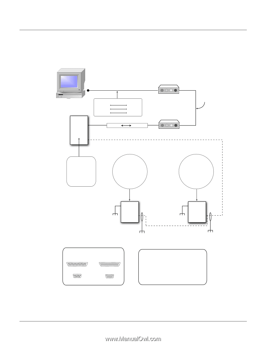
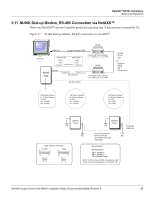
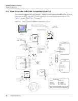
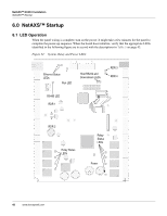
NetAXS™ NX4S1 Installation System Configuration 5.11 M-56K Dial-up Modem, RS-485 Connection via NetAXS™ Thirty-one NetAXS™ Access Controller panels for each drop line. It has not been reviewed by UL. Figure 27: M-56K Dial-up Modem, RS-485 Connection via NetAXS™ COM Port Straight Through Cable M-56K FAX/MODEM Terminal NetAXS Panel Female 9 Pin (RX) 2 (TX) 3 (Comm) 5 Male 25 Pin 3 (RX) 2 (TX) 7 (Comm) CBL50 Male 9 Pin Male 25 Pin RS-232 (50 ft.) Remote DIP Switch Settings (1, 3, 8 ON) (2, 4, 5, 6, 7 OFF) M-56K FAX/MODEM Remote DIP Switch Settings (1, 3, 8 ON) (2, 4, 5, 6, 7 OFF) RS-485 (4,000 ft.) Analog Phone Line Dedicated analog phone line recommended DIP Switch Settings S1-S5 Panel Address S6: ON J36: CLOSED J37: CLOSED DIP Switch Settings S1-S5 Panel Address S6: OFF J36: CLOSED J37: CLOSED DIP Switch Settings S1-S5 Panel Address S6: OFF J36: OPEN J37: OPEN NetAXS Panel EG EG NetAXS Panel EG See RS-485 Cable Note It is recommended to Earth Ground (EG) EG each NetAXS enclosure Individually DB 9 / DB 25 Connectors Female 13 1 Male 13 1 25 5 14 1 25 5 14 1 96 96 RS-485 Cable NetAXS Panels TB7-1 (RS485+) TB7-2 (RS485-) TB7-3 (RS485 COM) 4,000 ft. (1,200 m) max, 24 AWG, 2 twisted pairs with shield, 120 ohm, 23 pf (HAS part no. NCP2441-TN) NetAXS Access Control Unit NX4S1 Installation Guide, Document 800-00008, Revision A 37
-
 1
1 -
2
-
3
-
4
-
5
-
6
-
7
-
8
-
9
-
10
-
11
-
12
-
13
-
14
-
15
-
16
-
17
-
18
-
19
-
20
-
21
-
22
-
23
-
24
-
25
-
26
-
27
-
28
-
29
-
30
-
31
-
32
-
33
-
34
-
35
-
36
-
37
-
38
-
39
-
40
-
41
-
 42
42 -
 43
43 -
 44
44 -
 45
45 -
 46
46 -
 47
47 -
 48
48 -
 49
49 -
 50
50 -
 51
51 -
 52
52 -
53
-
54
-
55
-
56
-
57
-
58
-
59
-
60
-
61
-
62
-
63
-
64
-
65
-
66
-
67
-
68
-
69
-
70
-
71
-
72
-
73
 |
 |