Honeywell NX4S1 Installation Guide - Page 26
NX4S1 Control Output Wiring, Communications
 |
View all Honeywell NX4S1 manuals
Add to My Manuals
Save this manual to your list of manuals |
Page 26 highlights
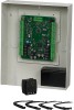
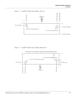
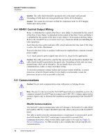
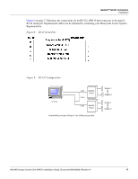
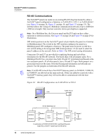
NetAXS™ NX4S1 Installation Installation Caution: The cable shield should be grounded only at the panel earth ground. Grounding at both ends can cause ground loops which can be disruptive. Caution: The system has not been verified for compliance with UL1076 Burglar Alarm units and systems. 4.4 NX4S1 Control Output Wiring Relay 1 is defaulted for control of the Door 1 lock, Relay 2 is defaulted for the control of the Door 2 lock, Relay 3 is defaulted for the control of the Door 3 lock, and Relay 4 is defaulted for the control of the Door 4 lock. Relays 5-8 are used as auxiliary relays. Refer to the NetAXS™ Access Control Unit User's Guide for details on controlling the relay operations. Each relay also has a green indicator LED, which indicates the relay state. If the relay is active, the LED is illuminated. Power for the door locks or auxiliary loads must be supplied from a separate external power supply. A UL-listed system's power supply must also be UL-listed for this application. Caution: The cable used must be sized for the current load and should be shielded. The cable shield should be grounded at the panel only. Grounding at both ends can cause ground loops which can be disruptive. Do not bundle these wires with communication, reader, or supervised input wiring. To minimize premature contract failure and increase system reliability, a contact protection circuit (HAS part number S-4) is highly recommended. Locate the protection circuit as close as possible to the load. 4.5 Communications Caution: Do not route communication wires with power or locking devices. Note: Because UL has reviewed the NetAXS™ panel only as a standalone system, the computer terminal, NetAXS™ gateway panel, and N-485_PCI-2 adapter appear in this section's figures only to illustrate the installation and programming of the NetAXS™ panel. RS-232 Communications The NetAXS™ panel communicates with a PC through a 50-foot RS-232 cable (HAS part number CBL50). Connect the RJ45 end of the cable to the jack on the NetAXS™ panel. The cable is used to provide communication to a single panel. A second cable can be used with another NetAXS™ control panel connected to a second COM (communication) port, which would enable eight readers to be used, see Figure 9, RS-232 Configuration. A USB converter is also available that will provide RS-232 communications. 16 www.honeywell.com
-
 1
1 -
2
-
3
-
4
-
5
-
6
-
7
-
8
-
9
-
10
-
11
-
12
-
13
-
14
-
15
-
16
-
17
-
18
-
19
-
20
-
 21
21 -
 22
22 -
 23
23 -
 24
24 -
 25
25 -
 26
26 -
 27
27 -
 28
28 -
 29
29 -
 30
30 -
 31
31 -
32
-
33
-
34
-
35
-
36
-
37
-
38
-
39
-
40
-
41
-
42
-
43
-
44
-
45
-
46
-
47
-
48
-
49
-
50
-
51
-
52
-
53
-
54
-
55
-
56
-
57
-
58
-
59
-
60
-
61
-
62
-
63
-
64
-
65
-
66
-
67
-
68
-
69
-
70
-
71
-
72
-
73
 |
 |