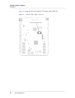
Honeywell NX4S1 Installation Guide - Page 25
Table 2, Default Supervised Input Assignments - nc
 |
View all Honeywell NX4S1 manuals
Add to My Manuals
Save this manual to your list of manuals |
Page 25 highlights
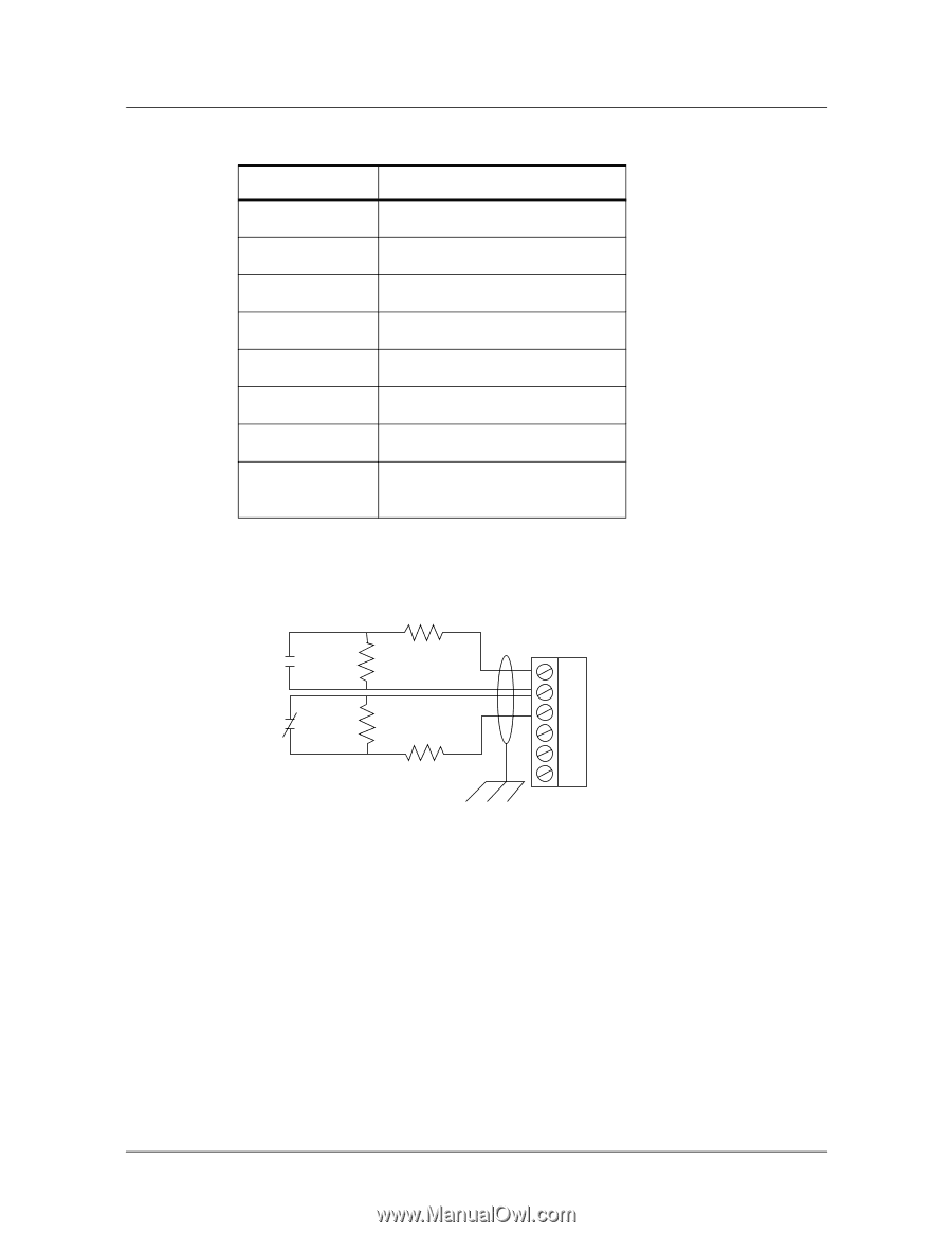
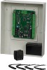
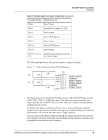
NetAXS™ NX4S1 Installation Installation Table 2 Default Supervised Input Assignments (continued) Terminal Position Default Function TB4-6 Door 2 Status TB8-1 External Power Supply AC FAIL TB8-3 Panel Tamper TB13-1 Door 3 REX (Egress) TB13-3 Door 3 Status TB13-4 Door 4 REX (Egress) TB13-6 Door 4 Status TB 5-6, 6-6, 11-6, Optional supervised input if not used 12-6 for a reader tamper The following figure shows the typical wiring for a supervised input. Figure 7: Typical Supervised Input Wiring Diagram NO 2.2K 2.2K NC 2.2K 2.2K TB 4 1 DOOR 1 EGRESS 2 COMMON 3 DOOR 1 STATUS 4 DOOR 2 EGRESS 5 COMMON 6 DOOR 2 STATUS The figure above shows standard 2,200 ohm resistors. The NetAXS™ panel accepts 1,000, 2,200, 4,700, or 10,000 ohm values. Note that both resistors must have the same value. See the NetAXS™ Access Control Unit User's Guide for instructions on selecting resistor options. In addition, the Tamper and External Power Fail, as well as the Reader and Panel tampers can be supervised and capable of being used as additional inputs if the default functionality is not needed. They also share a single common. The wire used for the inputs should be shielded and cannot exceed 30 ohms over the entire length of the cable. Remember that the distance from the panel to the door must be doubled to determine the total resistance. NetAXS Access Control Unit NX4S1 Installation Guide, Document 800-00008, Revision A 15
-
 1
1 -
2
-
3
-
4
-
5
-
6
-
7
-
8
-
9
-
10
-
11
-
12
-
13
-
14
-
15
-
16
-
17
-
18
-
19
-
 20
20 -
 21
21 -
 22
22 -
 23
23 -
 24
24 -
 25
25 -
 26
26 -
 27
27 -
 28
28 -
 29
29 -
 30
30 -
31
-
32
-
33
-
34
-
35
-
36
-
37
-
38
-
39
-
40
-
41
-
42
-
43
-
44
-
45
-
46
-
47
-
48
-
49
-
50
-
51
-
52
-
53
-
54
-
55
-
56
-
57
-
58
-
59
-
60
-
61
-
62
-
63
-
64
-
65
-
66
-
67
-
68
-
69
-
70
-
71
-
72
-
73
 |
 |