Honeywell NX4S1 Installation Guide - Page 54
Hardware Specifications
 |
View all Honeywell NX4S1 manuals
Add to My Manuals
Save this manual to your list of manuals |
Page 54 highlights
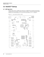
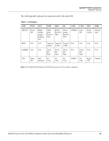
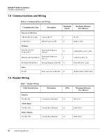
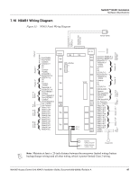
NetAXS™ NX4S1 Installation Hardware Specifications 7.0 Hardware Specifications 7.1 Relay Contacts Four Form-C SPDT relays: • 10 A @ 28 VDC resistive load • 5 A @ 28 VDC inductive load 7.2 Reader Interface • Reader Output Voltage ranges from 11.2 VDC to 12.4 VDC. The maximum Reader Output Current is 600 mA. • Reader LED Output: Open collector driver capable of sinking up to 8 mA. • Reader Tamper: Supervised or non-supervised input. • Reader Data Input: TTL compatible inputs. • Reader Buzzer Output: Open collector driver capable of sinking 8 mA at 15 VDC. 7.3 NX4S1 Wire Requirements • Power: One twisted pair shielded, 18 AWG. • RS-485: 24 AWG, 4,000 ft. (1,200 m) max, twisted pairs with shield, 120 ohm, 23 pf (HAS part number NC2441-TN). • RS-232: Use cable supplied with installation kit (HAS part number CBL50). Maximum distance per COM port is 50 ft. • Supervised Inputs: One twisted pair per input, shielded 30 ohms maximum. • Outputs: As required by load. • Readers: 7 conductors, 18 AWG, shielded, 500 ft. (150 m) max. 7.4 Maximum Output Loading • Maximum current for any of the four reader outputs is 600 mA. • Maximum current for each of the two auxiliary outputs on the NetAXS™ panel is 500 mA. • Maximum battery charge current for the single battery is 350 mA. • Maximum combined current of the four reader outputs and the two auxiliary outputs is 600 mA. • Maximum combined current of the two auxiliary outputs (if used without the four reader outputs) is 500 mA. Notes: • Each of the eight relay output contacts on the panel is rated for either 10 A at 28 VDC (resistive) or 5 A at 28 VDC (inductive). However, they are powered from a separate power supply. • A UL-listed system's power supply must also be UL-listed for this application. 44 www.honeywell.com
-
 1
1 -
2
-
3
-
4
-
5
-
6
-
7
-
8
-
9
-
10
-
11
-
12
-
13
-
14
-
15
-
16
-
17
-
18
-
19
-
20
-
21
-
22
-
23
-
24
-
25
-
26
-
27
-
28
-
29
-
30
-
31
-
32
-
33
-
34
-
35
-
36
-
37
-
38
-
39
-
40
-
41
-
42
-
43
-
44
-
45
-
46
-
47
-
48
-
 49
49 -
 50
50 -
 51
51 -
 52
52 -
 53
53 -
 54
54 -
 55
55 -
 56
56 -
 57
57 -
 58
58 -
 59
59 -
60
-
61
-
62
-
63
-
64
-
65
-
66
-
67
-
68
-
69
-
70
-
71
-
72
-
73
 |
 |