Konica Minolta ProJet 160 Cube3 User Guide - Page 23
to continue°
 |
View all Konica Minolta ProJet 160 manuals
Add to My Manuals
Save this manual to your list of manuals |
Page 23 highlights
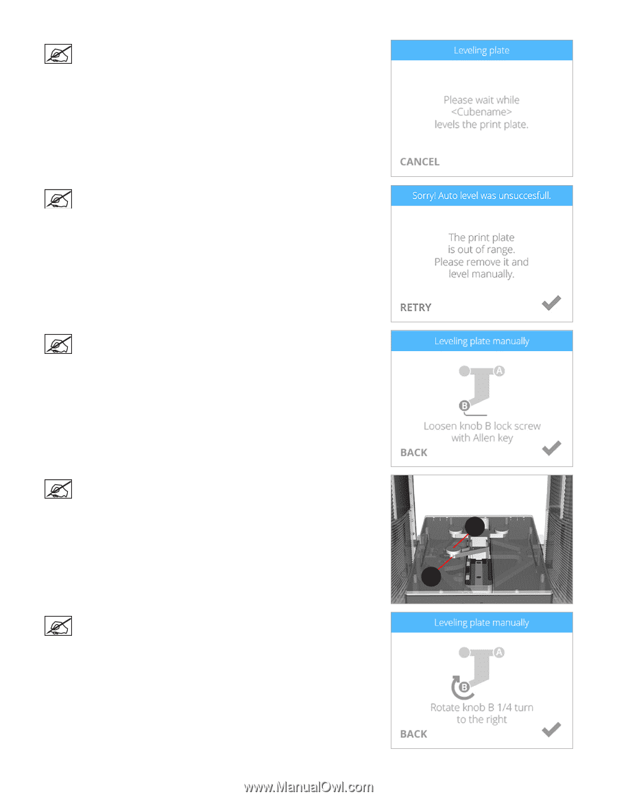
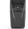
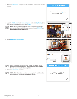
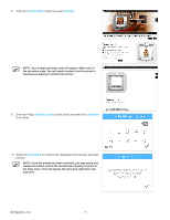
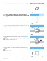
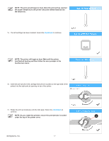
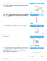
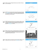
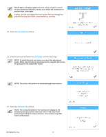
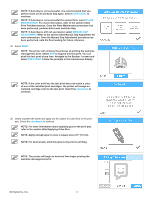
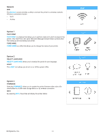
NOTE: The printer will begin the Auto Level procedure. This may take a few minutes. NOTE: If the print pad is not level, remove the print pad and select the checkmark to continue. The print pad is magnetically attached to the adjustment knobs. To remove it, lift up the front of the print pad and pull it out of the printer. NOTE: Follow the instructions on the touchscreen display. Use the included 1.5 mm Allen wrench to loosen the lock screws securing the adjustment knobs to the bracket before turning the knobs. Select the checkmark to continue. NOTE: The lock screw (1) is located just below the adjustment knob (2). The lock screw for adjustment knob B can be accessed from the front of the printer. The lock screw for adjustment knob A can be accessed from behind the printer. NOTE: Follow the instructions on the touchscreen display. Once the adjustments have been made, select the checkmark to continue. 2 1 3D Systems, Inc. 19
-
 1
1 -
2
-
3
-
4
-
5
-
6
-
7
-
8
-
9
-
10
-
11
-
12
-
13
-
14
-
15
-
16
-
17
-
 18
18 -
 19
19 -
 20
20 -
 21
21 -
 22
22 -
 23
23 -
 24
24 -
 25
25 -
 26
26 -
 27
27 -
 28
28 -
29
-
30
-
31
-
32
-
33
-
34
-
35
-
36
-
37
-
38
-
39
-
40
-
41
-
42
-
43
-
44
-
45
-
46
-
47
-
48
-
49
-
50
-
51
-
52
-
53
-
54
-
55
-
56
-
57
-
58
-
59
-
60
-
61
-
62
-
63
-
64
-
65
-
66
-
67
-
68
-
69
-
70
-
71
-
72
-
73
-
74
-
75
-
76
-
77
-
78
-
79
-
80
-
81
-
82
-
83
-
84
-
85
-
86
-
87
-
88
-
89
-
90
-
91
-
92
-
93
-
94
-
95
-
96
-
97
-
98
-
99
-
100
-
101
-
102
 |
 |